Method for inhibiting generation of internal defects of aluminum alloy resistance spot welding nugget

A technology of resistance spot welding and internal defects, which is applied in resistance welding equipment, manufacturing tools, welding equipment, etc., can solve problems such as internal defects of high-strength aluminum alloy spot welding nuggets, so as to improve the strength of solder joints, reduce stress, and suppress internal defects. The effect of the crack

Active Publication Date: 2021-03-30
SHANGHAI INST OF OPTICS & FINE MECHANICS CHINESE ACAD OF SCI
View PDF8 Cites 6 Cited by
  • Summary
  • Abstract
  • Description
  • Claims
  • Application Information

AI Technical Summary

Problems solved by technology

[0004] In order to solve the problem that internal defects are prone to appear inside the high-strength aluminum alloy spot welding nugget, the present invention proposes a method for suppressing the generation of internal defects in the aluminum alloy resistance spot welding nugget method

Method used


Image

  • Method for inhibiting generation of internal defects of aluminum alloy resistance spot welding nugget
  • Method for inhibiting generation of internal defects of aluminum alloy resistance spot welding nugget
  • Method for inhibiting generation of internal defects of aluminum alloy resistance spot welding nugget

Examples


Embodiment 1

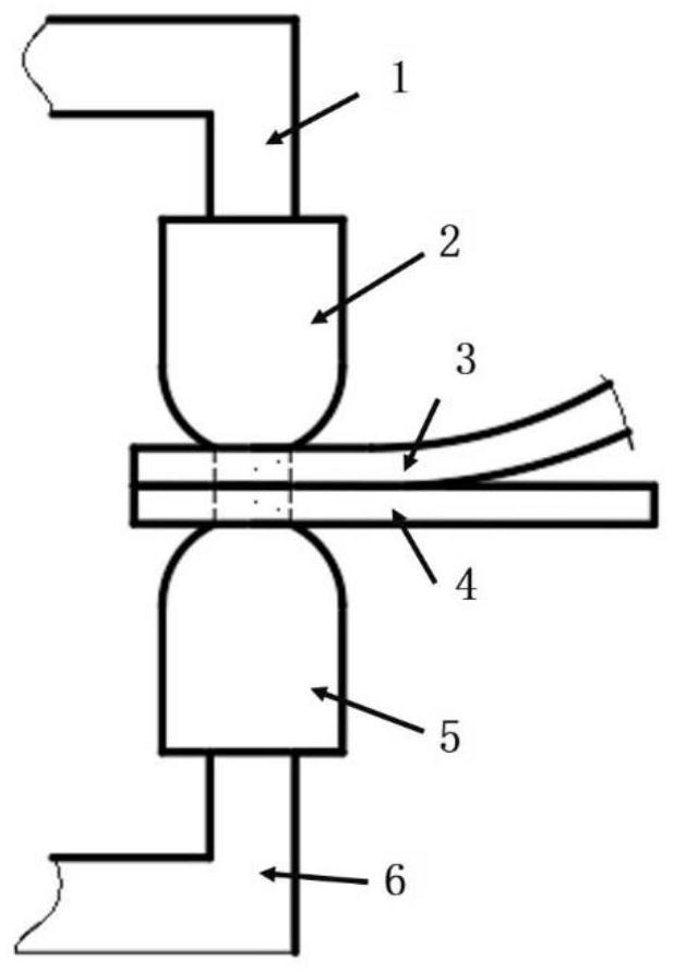
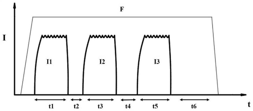
[0041] Two 7075-T6 aluminum alloy workpieces with a thickness of 2mm are stacked together to form a laminate, which is placed on the resistance spot welding equipment so that both ends of the laminate are in contact with the welding electrode cap. Such as figure 2 As shown, firstly, a constant pressure F of 4000N is applied to the stack by welding the electrode caps on both sides. The duration of this pressure is preferably 50ms-300ms, more preferably 60-200ms, and then the first welding Current I1, the current value is reduced to zero after passing through the first stage of welding current for a period of time, entering the first cooling stage, and then passing through the second stage of welding current I2 after cooling, and then reducing the current value to zero, entering the second stage In the cooling stage, after the second cooling stage, the third stage of welding current I3 is passed, and finally enters the third cooling stage, which is the pressure holding stage. ...

Embodiment 1

[0044] Embodiment 1 Comparative Example

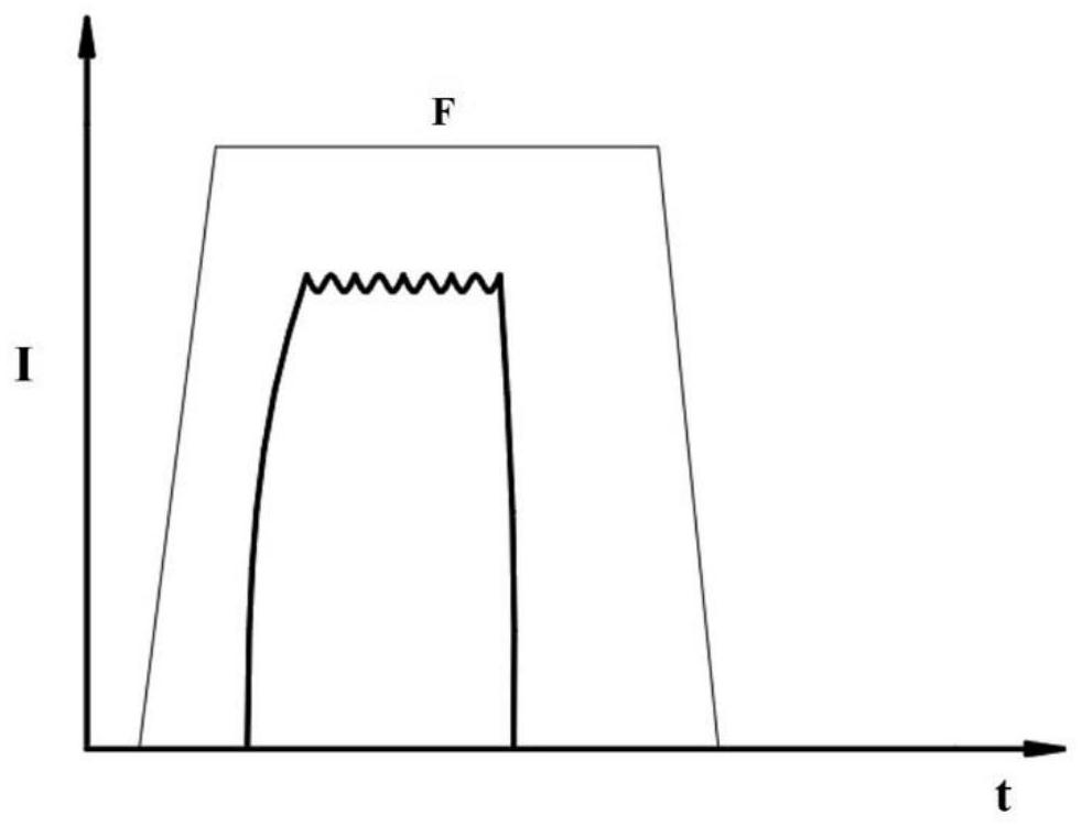
[0045] Such as image 3 Shown, for not using the method of the present invention, adopt the electrode cap identical with embodiment 1, use the method for welding of common single pulse, wherein welding current I is 30KA, and welding time t is 150ms, and electrode pressure F is 4000N, hold pressure The time is 50ms; Figure 7 The metallographic diagram of the cross-section of the solder joint obtained in this example shows that there are a large number of defects such as shrinkage cavities and cracks inside the nugget.

Embodiment 2

[0047] Such as Figure 5 and 9 As shown, this embodiment is similar to Embodiment 1, the difference is that the cross-sectional shape of the welding electrode cap is a concave electrode cap with a ring-shaped protrusion on the edge.

[0048] Such as Figure 8 Shown is the cross-sectional metallographic diagram of the aluminum alloy solder joint obtained by using the method of this embodiment. It can be seen that there are basically no shrinkage cavities, cracks, etc. inside the nugget.


PUM

PropertyMeasurementUnit
thicknessaaaaaaaaaa

Abstract

The invention discloses a method for inhibiting generation of internal defects of an aluminum alloy resistance spot welding nugget, and belongs to the technical field of resistance spot welding. A welding current is divided into an electrifying heating stage, a cooling stage and a pressure maintaining stage, wherein in the electrifying heating stage, the current amplitude of the welding current is15KA-60KA, and the electrifying time is 50ms-200ms; and in the cooling stage, the current is 0-15KA, and the cooling time is 2ms-40ms. According to the welding method, due to the existence of the cooling stage, welding heat input is stable, and internal stress of a welding spot is reduced, so that the generation of the defects such as cracks and air holes in the nugget is inhibited, and the effect of improving the strength of the welding spot is achieved.

Description

technical field [0001] The invention belongs to the technical field of resistance spot welding, and in particular relates to a method for suppressing internal defects of an aluminum alloy resistance spot welding nugget. Background technique [0002] Aluminum alloy resistance spot welding is an important manufacturing process in the current industry. Due to the high specific strength of aluminum alloy, it is a kind of material that is widely used in automobile, aerospace and other industries. During the spot welding process, low melting point eutectics are easily formed inside the nugget. During the spot welding cooling process, the solidification shrinkage is serious, and the tensile stress is relatively large. Defects such as cracks and shrinkage cavities are easily formed inside the nugget, and the existence of defects will be extremely large. The reduction of the mechanical properties of the solder joints leads to permanent failure of the welded structure under lower str...

Claims


Application Information

Patent Timeline
Patent Type & Authority Applications(China)
IPC IPC(8): B23K11/11B23K11/18B23K11/24B23K31/02
CPCB23K11/115B23K11/24B23K11/185B23K31/02
Inventor 王艳俊杨上陆
Owner SHANGHAI INST OF OPTICS & FINE MECHANICS CHINESE ACAD OF SCI
Why Eureka
Try Eureka