Eureka AIR delivers breakthrough ideas for toughest innovation challenges, trusted by R&D personnel around the world.

Vehicle control method, device, device and medium based on obstacle recognition

A technology for obstacle recognition and vehicle control, applied in the computer field

Active Publication Date: 2022-05-17
BEIJING BAIDU NETCOM SCI & TECH CO LTD
View PDF0 Cites 0 Cited by
  • Summary
  • Abstract
  • Description
  • Claims
  • Application Information

AI Technical Summary

Problems solved by technology

[0004] Various complex situations will appear during the actual driving of the vehicle, such as the situation where obstacles appear on the edge of the lane and need to be avoided, but the existing path planning method is difficult to flexibly match this roadside obstacle avoidance situation

Method used


Image

  • Vehicle control method, device, device and medium based on obstacle recognition
  • Vehicle control method, device, device and medium based on obstacle recognition
  • Vehicle control method, device, device and medium based on obstacle recognition

Examples


Embodiment 1

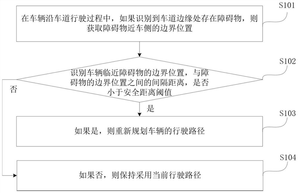
[0068] figure 1 It is a schematic flow chart of a vehicle control method based on obstacle recognition provided in Embodiment 1 of the present application. The embodiment of the present application can be applied to replanning the driving path of the vehicle according to the distance between the obstacle and the vehicle while the vehicle is driving In a scenario, the method can be executed by a vehicle control device based on obstacle recognition, which can be implemented by software and / or hardware, and can be integrated inside the electronic device. In this embodiment, the electronic device may be any hardware device with a data processing function, such as a vehicle-mounted computer, an intelligent driving instrument, and the like. The method specifically includes the following steps:

[0069] S101. When the vehicle is running along the lane, if it is recognized that there is an obstacle at the edge of the lane, acquire a boundary position of the obstacle near the vehicle....

Embodiment 2

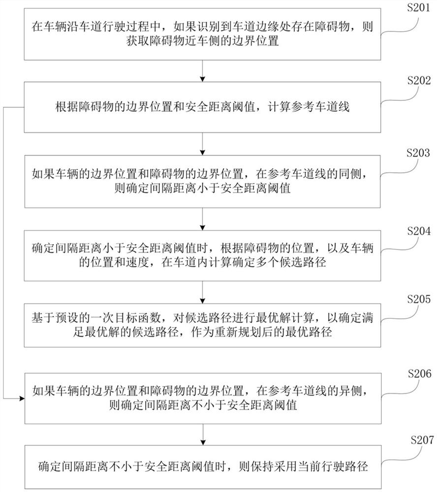
[0092] From the above analysis, it can be seen that in the embodiment of the present application, the driving path of the vehicle is re-planned by recognizing that the distance between the boundary position of the vehicle and the boundary position of the obstacle is less than the safety distance.

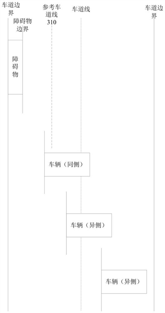
[0093] In a specific implementation process, identifying whether the vehicle is close to the boundary position of the obstacle, and whether the distance between the boundary position of the obstacle and the boundary position of the obstacle is less than a safety distance threshold includes: according to the boundary position of the obstacle and the The safety distance threshold is used to calculate the reference lane line; if the boundary position of the vehicle and the boundary position of the obstacle are on the same side of the reference lane line, it is determined that the separation distance is less than the safety distance threshold; if the If the boundary position of the vehic...

Embodiment 3

[0114] In order to achieve the above purpose, Embodiment 3 of the present application proposes a vehicle control device based on obstacle recognition. Figure 5 It is a schematic structural diagram of a vehicle control device based on obstacle recognition provided in Embodiment 3 of the present application.

[0115] Such as Figure 5 As shown, the vehicle control device based on obstacle recognition in the embodiment of the present application includes: an acquisition boundary position module 510 , an identification interval distance module 520 and a control module 530 .

[0116] Wherein, the acquiring boundary position module 510 is used for acquiring the boundary position of the vehicle near the side of the obstacle if it is recognized that there is an obstacle at the edge of the lane while the vehicle is running along the lane;

[0117] The identifying separation distance module 520 is used to identify whether the separation distance between the boundary position of the ve...


PUM


Abstract

The embodiment of the present application discloses a vehicle control method, device, device and medium based on obstacle recognition, and relates to automatic driving technology in the field of computer technology. The vehicle control method based on obstacle identification includes: when the vehicle is running along the lane, if an obstacle is recognized at the edge of the lane, obtaining the boundary position of the obstacle near the vehicle; identifying the boundary position of the vehicle close to the obstacle, and Whether the distance between the boundary positions of the obstacles is less than the safety distance threshold; if so, re-plan the driving path of the vehicle. The embodiment of the present application realizes that when the distance between the boundary position of the obstacle and the boundary position of the vehicle adjacent to the obstacle is less than the safety distance threshold, the vehicle driving path is re-planned to optimize the vehicle path planning method and flexibly match the driving speed of the vehicle. Special case.

Description

technical field [0001] The embodiments of the present application relate to computer technology, in particular to automatic driving technology, and in particular to a vehicle control method, device, device and medium based on obstacle recognition. Background technique [0002] In the automatic driving technology of the vehicle, the basic control logic is to plan the vehicle path according to the recognition result of the surrounding environment of the vehicle, and then control the driving of the vehicle according to the planning result. [0003] Existing path planning technologies are based on the lanes in which vehicles drive. Specifically, in the electronic map used by the vehicle, the lane for the vehicle to drive can be determined, and generally the center line of the lane is used as the lane line. Lane lines are an important reference factor for vehicle path planning. When the vehicle is driving along the lane line, it continuously detects the surrounding environment ...

Claims


Application Information

Patent Timeline
Patent Type & Authority Patents(China)
IPC IPC(8): B60W30/08B60W30/09B60W60/00G08G1/16
CPCB60W30/08B60W30/09G08G1/165G08G1/166
Inventor 吕雷兵姚冬春朱帆薛晶晶孙勇义
Owner BEIJING BAIDU NETCOM SCI & TECH CO LTD
Why Eureka
Eureka Blog
Learn More