
Unmanned aerial vehicle flight simulation method and system

A flight simulation and UAV technology, applied in the field of flight simulation, can solve the problem of high cost, achieve comprehensive and reliable results, reduce economic costs and time costs, and save time and energy.

Pending Publication Date: 2021-03-30
GENERAL ENG RES INST CHINA ACAD OF ENG PHYSICS
View PDF9 Cites 0 Cited by
  • Summary
  • Abstract
  • Description
  • Claims
  • Application Information

AI Technical Summary

Problems solved by technology

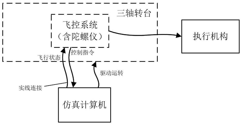
[0002] like figure 1 As shown, the common practice of UAV flight simulation is to realize the three-axis turntable in the laboratory. The output command is connected to the simulation computer. After the simulation computer receives the instructions of each actuator, it runs the dynamic model of the UAV in real time and calculates the status information (position, speed, acceleration, etc.) of the UAV. The fixed data format transmits the data to the flight control system, and at the same time drives the movement of the turntable so that the flight control system can perceive the angular velocity information in real time. After receiving all the information, the flight control system can calculate the required control in real time according to the mission instructions and control laws. command, and send it out, so that it goes round and round to complete the ground simulation flight process of the UAV, but the problem with this method is that the three-axis turntable is a high-precision, high-performance precision instrument and equipment, and the cost of running it once is too high. It is equivalent to important airborne equipment, so it is especially not suitable for small and medium-sized low-cost UAVs

Method used


Image

  • Unmanned aerial vehicle flight simulation method and system
  • Unmanned aerial vehicle flight simulation method and system
  • Unmanned aerial vehicle flight simulation method and system

Examples


Embodiment Construction

[0023] In order to make the purpose, technical solutions and advantages of the embodiments of the present invention more clear, the technical solutions in the embodiments of the present invention will be clearly and completely described below in conjunction with the drawings in the embodiments of the present invention. Apparently, the described embodiments are some, but not all, embodiments of the present invention. The components of the embodiments of the invention generally described and illustrated in the figures herein may be arranged and designed in a variety of different configurations.

[0024] Accordingly, the following detailed description of the embodiments of the invention provided in the accompanying drawings is not intended to limit the scope of the claimed invention, but merely represents selected embodiments of the invention. Based on the embodiments of the present invention, all other embodiments obtained by persons of ordinary skill in the art without creative...


PUM


Abstract

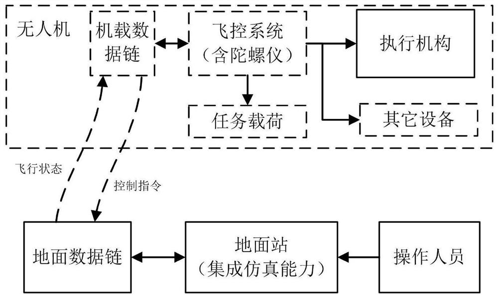
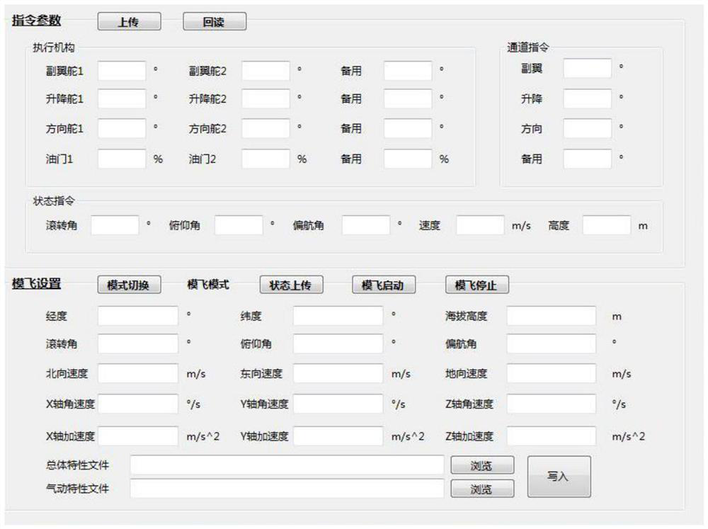
The invention discloses an unmanned aerial vehicle flight simulation method and system, and relates to the field of flight simulation. The method comprises the steps of: S1, importing initial data into a ground station and transmitting the data to an unmanned aerial vehicle; S2, acquiring an execution mechanism output instruction according to a simulated flight state parameter and a flight plan, and transmitting the execution mechanism output instruction and periodic telemetry data to the ground station; S3, outputting and displaying periodic telemetry data in real time by the ground station,acquiring a next simulated flight state parameter according to the simulated flight state parameter, the execution mechanism output instruction and an unmanned aerial vehicle kinetic model, transmitting the next simulated flight state parameter to the unmanned aerial vehicle, and entering S2; the system comprises a data input module, a simulation module, a flight control system and a display module. The ground station has the dynamic simulation calculation capability, the unmanned aerial vehicle can perform flight mode switching, and the ground station can send the flight state of the unmannedaerial vehicle in real time, so that the simulated flight test can be completed without a three-axis turntable, clamps and cables do not need to be customized, and the economic and time costs are reduced; the whole "simulated flight" is simplified, and the time and energy of personnel are saved.

Description

technical field [0001] The invention relates to the field of flight simulation, in particular to a flight simulation method and system for an unmanned aerial vehicle. Background technique [0002] Such as figure 1 As shown, the common practice of UAV flight simulation is to realize the three-axis turntable in the laboratory. The output command is connected to the simulation computer. After the simulation computer receives the instructions of each actuator, it runs the dynamic model of the UAV in real time and calculates the status information (position, speed, acceleration, etc.) of the UAV. The fixed data format transmits the data to the flight control system, and at the same time drives the movement of the turntable so that the flight control system can perceive the angular velocity information in real time. After receiving all the information, the flight control system can calculate the required control in real time according to the mission instructions and control laws....

Claims


Application Information

Patent Timeline
IPC IPC(8): B64F5/60
CPCB64F5/60
Inventor 邓坤黄佳陈强洪袁鸣周欢
Owner GENERAL ENG RES INST CHINA ACAD OF ENG PHYSICS
Learn More