Manufacturing method of water injection packer, water injection packer easy to release, and construction method

A manufacturing method and packer technology, which is applied in the directions of sealing/packing, earthwork drilling, mining fluids, etc., and can solve the problems of complex unsealing mechanism, water scaling and easy jamming of water injection packers, etc. , to achieve the effect of avoiding poor thread connection performance, avoiding poor tensile performance, and improving the success rate of unsealing

Pending Publication Date: 2021-03-30
CHINA PETROLEUM & CHEM CORP +1
View PDF2 Cites 0 Cited by
  • Summary
  • Abstract
  • Description
  • Claims
  • Application Information

AI Technical Summary

Problems solved by technology

[0008] The purpose of the present invention is to solve the problem that the unsealing mechanism of the conventional water injection packer is complex, and it is easy to get stuck when encountering formation sand or injection water scaling, and to provide a water injection packer manufacturing method and an easy-to-release water injection packer and its construction. Method, through the comprehensive use of conventional metal materials, drillable composite materials and soluble materials, the lifting and unsealing or casing milling and unsealing operations are more reliable than conventional packers, and the current conventional metal material water injection packers are easy to get stuck The problem

Method used


Image

  • Manufacturing method of water injection packer, water injection packer easy to release, and construction method

Examples


Embodiment 2

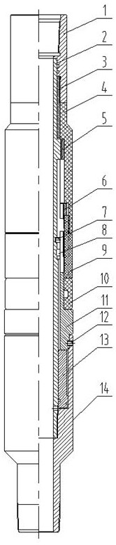
[0040] The upper body of the unblocking claw 3 is a cylindrical body, the lower body is a claw piece, an unlocking boss is provided at the bottom of the claw piece, and an unsealing shear nail assembly hole and an unlocking button are provided in the claw piece below the unlocking boss. Block mounting holes.

[0041] The claw piece of described unsealing claw 3 is provided with at least three pieces, and the unlocking boss outer diameter of claw piece bottom is greater than the inner diameter of sitting blockade ring 6, and the upper end of unlocking boss is provided with chamfer, is convenient to slide in and sits in the blockade ring 6, will Sit on the blockade ring 6 and stretch it out.

Embodiment 3

[0043] The upper outer wall of the central tube 2 is provided with a connecting step, the body of the connecting step is provided with an unsealing claw through the groove, and the outer wall is provided with threads to connect with the retaining ring 5; the liquid flow hole in the central tube 2 is connected to the bottom of the piston 13 Corresponding. The central pipe 2 blocks the unsealing claw 3 in the connection step of the upper outer wall while realizing the connection with the retaining ring 5 .

[0044] The unsealing claws in the connecting step of the central tube 2 match the number of claws of the unsealing claws 3 through the slots, and the outer wall of the central pipe 2 middle part is provided with an unsealing shear nail assembly groove and an unblocking block assembly groove, which are respectively connected with the unsealing claws. The unsealing scissors assembly hole at the lower part of the pawl 3 pawl sheet is connected with the unsealed shears 7 in the ...

Embodiment 4

[0046] The lower body of the setting claw 11 is a stepped cylinder, and the upper part is a claw piece. The number of claw pieces of the setting claw 11 is equal to that of the unsealing claw 3 and interlaced with the unlocking bosses of the unsealing claw 3. Connect with seat block ring 6.


PUM


Abstract

The invention relates to a manufacturing method of a water injection packer used for a water injection well in the petroleum industry, the water injection packer easy to release, and a construction method. A deblocking mechanism of the water injection packer easy to release is provided with a deblocking claw, a deblocking shear pin, and a deblocking lock block; the deblocking claw is arranged between a central pipe and an upper connector and an upper pressing sleeve and is in threaded connection with the upper connector; the outer diameter of the upper pressing sleeve and the outer diameter ofan upper spacer sleeve are larger than the outer diameter of the upper connector; the upper pressing sleeve and the upper spacer sleeve are connected through threads and installed above a rubber cylinder; the upper pressing sleeve, the upper spacer sleeve and the rubber cylinder are installed between the upper connector and a setting claw; the setting claw is connected with a lower connector through a setting shear pin; the upper portion of the central pipe is connected with a baffle ring, and the lower portion of the central pipe is connected with the lower connector; the delocking shear pinand the delocking lock block fix the delocking claw and the central pipe together; a setting lock ring is installed on the upper portion of the setting claw; the setting claw can move upwards along the setting lock ring in the setting process of the water injection packer; and a piston is installed between the central pipe and the lower connector. According to the manufacturing method of a waterinjection packer, the water injection packer easy to release, and a construction method, the relatively independent delocking mechanism is more reliable in work when being lifted for delocking.

Description

technical field [0001] The invention relates to a downhole water injection packer for an oil field water injection well, in particular to a manufacturing method of the water injection packer, an easy-release stuck water injection packer and a construction method. Background technique [0002] At present, compression packers such as Y341 are often used for layered water injection. There are generally multiple locking blocks between the setting mechanism and the unsealing mechanism of this type of packer. The sealing mechanism is connected as a whole. After the setting is completed, the unsealing mechanism is lifted up, the lock block moves, the unsealing mechanism is disengaged from the setting mechanism, and the unsealing mechanism is continuously lifted to realize the unsealing of the packer. [0003] The design of this type of packer structure involves the movement of multiple lock blocks during the unsealing process. In the event of sand spewing from the formation of the ...

Claims


Application Information

Patent Timeline
Patent Type & Authority Applications(China)
IPC IPC(8): E21B23/06E21B33/128E21B43/20E21B29/00
CPCE21B23/06E21B29/00E21B33/128E21B43/20
Inventor 张化强姜广彬李敢田浩然周景彩刘永顺张瑞霞
Owner CHINA PETROLEUM & CHEM CORP
Why Eureka
Try Eureka