
Solar street lamp

A technology for solar street lamps and solar panels, applied in the field of solar street lamps, can solve the problems of easy volatilization and dissipation, inability to effectively collect accumulated water, inability to clean the surface of the lampshade, etc., and achieve the effect of ensuring the wiping effect.

Active Publication Date: 2021-03-30
中山澳特浦光电有限公司
View PDF6 Cites 0 Cited by
  • Summary
  • Abstract
  • Description
  • Claims
  • Application Information

AI Technical Summary

Problems solved by technology

[0004] Although this patent document solves the problems existing in traditional street lamps to a certain extent, it also has the following shortcomings: simply passing through the accumulated water at night and early morning It is very volatile and lost during the day, and cannot effectively collect accumulated water, especially in summer when there are most mosquitoes, it is even more difficult to effectively obtain a large amount of accumulated water; at the same time, simply using the flushing effect generated by the flow of water cannot effectively clean the surface of the lampshade, especially for Some dead mosquitoes stuck to the surface of the lampshade

Method used


Image

  • Solar street lamp
  • Solar street lamp
  • Solar street lamp

Examples


Embodiment 1

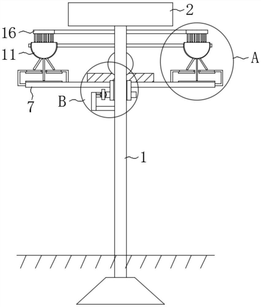
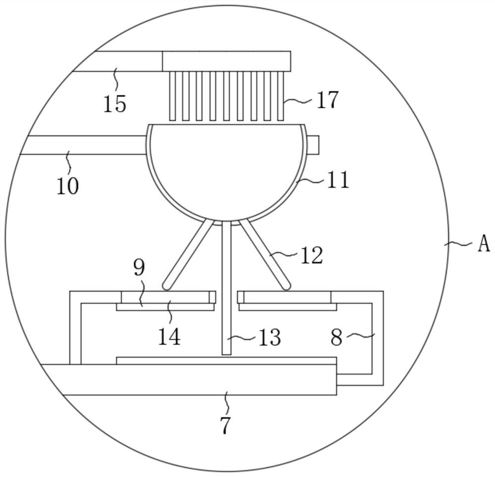
[0029] refer to Figure 1-4 , a solar street lamp, comprising a light pole 1, a solar panel 2, a mounting seat 3, a mounting pole 4, and a lampshade 5, a rotating seat 6 is installed on the light pole 1, and two rod bodies-7 are fixedly installed on the rotating seat 6 , two rod bodies 2 8 are fixedly installed on the two rod body 1 7, and a wiping sponge 9 is fixedly installed on the two rod body 1 7 and the four rod body 2 8;

[0030] There are two points worth noting above:

[0031] 1. The setting of the wiping sponge 9 is used to wipe the upper and lower surfaces of the lampshade 5 to improve the cleanliness of the surface.

[0032] 2. There are certain differences in the shapes of the two rods 2 8 located on the same rod 1 7, details can be found in the attached manual image 3 clearly seen in.

[0033] Two poles 10 are fixedly installed on the light pole 1, and a water collecting seat 11 is fixedly installed on the two poles 10, and the upper end of the water collecti...

Embodiment 2

[0045] refer to Figure 5 , Figure 6, the difference between this embodiment and Embodiment 1 is that the reciprocating structure is composed of a memory metal 2 24, a magnetic block 3, a magnetic block 25, a connecting rod, a magnetic block 2 and a directional movement assembly, and the frame The side of the second 21 close to the light pole 1 is fixedly installed with a memory metal 2 24, and one end of the memory metal 24 is fixedly installed with a magnetic block 3, and the end of the magnetic block 3 far away from the memory metal 2 24 is fixedly installed with a magnetic block through a connecting rod One 25, and the magnetism of the same side of the magnetic block three and the magnetic block one 25 is opposite, the side of the tooth plate 19 close to the memory metal two 24 is fixedly installed with the magnetic block two, and a directional movement assembly is installed between the magnetic block three and the frame two 21 The directional movement assembly is compos...


PUM


Abstract

The invention discloses a solar street lamp which comprises a lamp post, a solar cell panel, a mounting base, a mounting rod and a lampshade. A rotating base is rotatably mounted on the lamp post, twofirst rod bodies are fixedly mounted on the rotating base, two second rod bodies are fixedly mounted on each of the two first rod bodies, and wiping sponge is fixedly mounted on each of the two firstrod bodies and the four second rod bodies. Two first rods are fixedly installed on the lamp post, a water collecting base is fixedly installed on each of the two first rods, the upper end of each water collecting base is open, each of the two water collecting bases is fixedly communicated with two first water outlet pipes and a second water outlet pipe, the second rod bodies are provided with through holes matched with the first water outlet pipes, and the through holes are located directly above the corresponding wiping sponge. The solar street lamp has the advantages that the collected dewis used for wetting the corresponding wiping sponge, and then the wiping sponge is driven to rotate by utilizing the characteristics of the memory metal when the temperature is relatively high in thedaytime, so that the surface of the lamp shade is wiped, and the lighting effect during use at night is ensured.

Description

technical field [0001] The invention relates to a street lamp, in particular to a solar street lamp. Background technique [0002] Street lamp is a device installed on the side of the road to illuminate at night, but it will attract a lot of mosquitoes with phototaxis when working at night, and often there will be more mosquito corpses on the lampshade surface of the street lamp, and the lampshade is also easy to adhere More dust will affect the lighting effect of street lamps. [0003] After searching, the Chinese authorized invention patent with the patent number CN106764893B discloses a solar street lamp, which includes a base under the ground and a bracket fixed on the base. A circular water storage tank is arranged on the top of the bracket; There is a solar storage board fixedly installed on the bracket; a pole fixedly installed on the bracket is arranged under the solar storage board, and a lighting lamp electrically connected to the solar storage board is installed ...

Claims


Application Information

Patent Timeline
Patent Type & Authority Applications(China)
IPC IPC(8): F21S9/03B08B1/00B08B1/04B08B3/04E03B3/02F21W131/103
CPCF21S9/035B08B3/04E03B3/02F21W2131/103B08B1/143B08B1/32Y02B20/72Y02A20/108
Inventor 吴巨才
Owner 中山澳特浦光电有限公司
Learn More