
Circuit compatible with TEC and Header in optical module and application method

An optical module and circuit technology, used in the coupling of optical waveguides, conversion equipment without intermediate conversion to AC, and optical guides, etc., can solve problems such as low practicability, inability to achieve Heater compatibility, and poor cost controllability. Achieve the effect of good practicability, good equipment cost controllability and low cost price

Active Publication Date: 2021-03-30
四川华拓光通信股份有限公司
View PDF12 Cites 0 Cited by
  • Summary
  • Abstract
  • Description
  • Claims
  • Application Information

AI Technical Summary

Problems solved by technology

[0003] However, in the prior art, when the optical module is connected to the TEC, the MCU is usually directly connected to the TEC, or the MCU is connected to the TEC through a driving circuit. Therefore, when the optical module is used, it cannot be compatible with the Heater when using the TEC circuit. , so the cost controllability is not good, and the practicability is not strong

Method used


Image

  • Circuit compatible with TEC and Header in optical module and application method
  • Circuit compatible with TEC and Header in optical module and application method

Examples


Embodiment Construction

[0029] The present invention will be further described in detail below in conjunction with the accompanying drawings, so that those skilled in the art can implement it with reference to the description.

[0030] It should be understood that terms such as "having", "comprising" and "including" as used herein do not entail the presence or addition of one or more other elements or combinations thereof.

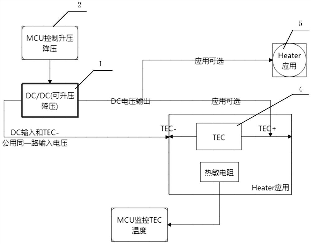
[0031] figure 1 It shows a circuit implementation form compatible with TEC and Heater in an optical module according to the present invention, which includes:

[0032] A power conversion chip DC / DC 1 for step-up / step-down, which provides working voltage for TEC and Heater through the DC / DC set in the optical module;

[0033] A microcontroller MCU 2 connected to the DC / DC to control its step-up / step-down range, which is used to provide a suitable working voltage for TEC and Heater by selecting different working modes;

[0034] The voltage output end of the DC / DC can be selective...


PUM


Abstract

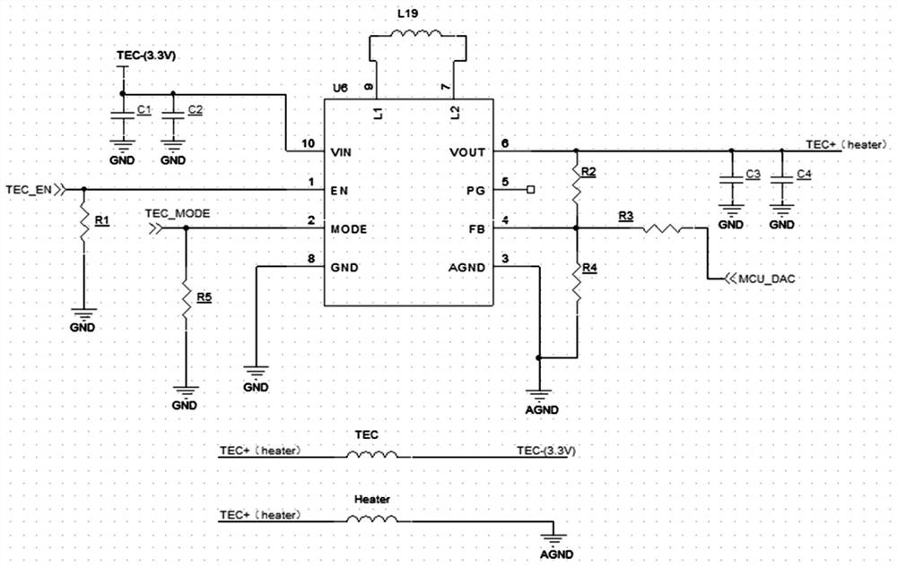
The invention discloses a circuit compatible with TEC and Header in an optical module and an application method of the circuit. The circuit comprises a power conversion chip DC / DC for boosting / reducing voltage; a MCU, connected with the DC / DC so as to control the voltage boosting / reducing amplitude of the DC / DC; the voltage output end of the DC / DC is selectively connected with the semiconductor chilling plate TEC or the heater Heater; wherein the DC / DC and a TEC- pin of the TEC share one path of 3.3 V input voltage; a TEC+ pin of the TEC is connected with a DC / DC voltage output pin, so that the working voltage of the TEC is controlled between 1 V and 5.5 V; A voltage input pin of the Heater is connected with a voltage output pin of the DC / DC, and the voltage output pin of the Heater is configured to be grounded, so that the working voltage range of the Heater is controlled between 0 V and 3.3 V. According to the circuit compatible with the TEC and the Heater in the optical module and the application method of the circuit, the DCDC is used in the optical module, meanwhile, the pins of the DCDC are limited in a matched mode, so that the circuit is compatible with the TEC and the Heater in the optical module, and by sharing the circuit, the equipment cost controllability and practicability are good.

Description

technical field [0001] The invention relates to the field of optical module communication. More specifically, the present invention relates to a circuit compatible with TEC (Thermoelectric Cooler, semiconductor cooling chip) and Heater (heater) in an optical module and an application method thereof. Background technique [0002] At present, in the medium and long-distance high-speed optical components, the stability of the emission wavelength is highly required. Because the working temperature of the optical component will affect the stability of the emission wavelength, a large number of MWDM, LWDM, and DWDM products use TEC to control the temperature of the laser in the optical component to keep the emission wavelength of the laser in the optical component stable, while CWDM Products with wide wavelength range or cost reduction are mainly controlled by Heater circuit. [0003] However, in the prior art, when the optical module is connected to the TEC, the MCU is usually ...

Claims


Application Information

Patent Timeline
Patent Type & Authority Applications(China)
IPC IPC(8): G02B6/42H02M3/04
CPCG02B6/4274G02B6/4271H02M3/04
Inventor 熊伟霖胡仕丹陈丽丁征
Owner 四川华拓光通信股份有限公司
Learn More