Electromechanical-hydraulic piston actuator and brake system

An actuator and piston-type technology, applied in the direction of brakes, brake transmissions, transmissions, etc., can solve problems such as uncertain re-connection, and achieve the effect of compact structure

Active Publication Date: 2021-03-30
CONTINENTAL AUTOMOTIVE TECH GMBH
View PDF5 Cites 3 Cited by
  • Summary
  • Abstract
  • Description
  • Claims
  • Application Information

AI Technical Summary

Problems solved by technology

[0021] The disadvantage of the described linear actuator is that the coupling is only achieved when the angle of rotation of the coupling disc and the motor coincides, so that the coupling disc can "thread" into the slot of the rotor of the motor
So not sure if it's safe to reconnect after a successful disconnect

Method used


Image

  • Electromechanical-hydraulic piston actuator and brake system
  • Electromechanical-hydraulic piston actuator and brake system
  • Electromechanical-hydraulic piston actuator and brake system

Examples


Embodiment Construction

[0056] In all figures, the same parts are indicated by the same reference numerals.

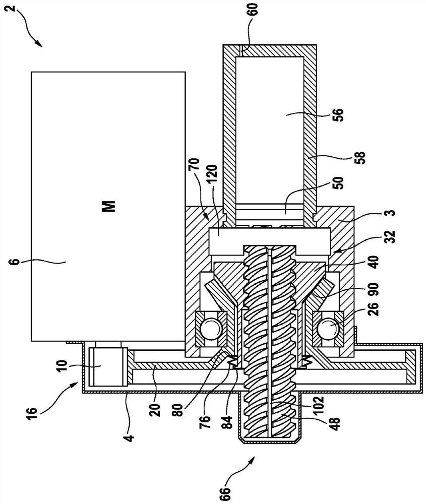
[0057] figure 1 The electromechanical-hydraulic piston actuator 2 shown in includes a housing with a load-bearing structure 3 , a transmission cover 4 and an electric motor 6 with a stator and a rotor 10 , which is coupled to a drive element 20 via a rotation-rotation transmission 16 , the rotation-rotation transmission mechanism at figure 1 is shown as a gear pair, but could just as easily be shown as a belt drive. When the rotor 10 rotates, the drive element 20 , which is rotatably mounted in a bearing 26 in the carrying structure 3 , is caused to rotate. The actuator 2 has a rotation-translation transmission mechanism 32 driven by a drive element 20 comprising a rotatable nut 40 and a screw 48 arranged not to rotate but movable in its axial direction. The piston 50 is coupled with the screw 48 in the axial direction.

[0058] To build up the pressure, the piston 50 is movable in a hydr...


PUM


Abstract

The invention relates to an electromechanical-hydraulic piston actuator (2) for providing pressurized pressure medium for a brake system of a vehicle, comprising an electric motor (6) having a statorand a rotor (10), a rotation-translation gearing (32) which is driven in rotation by the electric motor (6) and which has a rotatable nut (40) and a threaded rod (48) that is prevented from rotating and mounted so as to be able to slide in its axial direction, a piston (50) coupled to the threaded rod (48) in the axial direction thereof, a hydraulic cylinder (58) with a hydraulic chamber (56) which is filled with pressure medium and into which the piston (50) can be displaced, by a translatory movement of the threaded rod (48), from a retracted piston position in the direction of an advanced piston position in order to pressurize the pressure medium and / or expel same from the chamber (56), and a hydraulic connection (60) which is connected to the chamber (56) and via which pressure mediumcan be expelled from the chamber (56), and a supporting structure (3) to which the electric motor (6), the rotation-translation gearing (32) and the hydraulic cylinder (58) are attached, there being provided, between the rotor (10) of the electric motor (6) and the nut (40), an isolation device (70) for piston-travel-controlled isolation of the rotary coupling.

Description

technical field [0001] The invention relates to an electro-hydraulic piston actuator for supplying a pressurized / under pressure pressure medium to a brake system of a vehicle, comprising: [0002] · Electric motors with a stator and a rotor, [0003] Rotary-translational transmission driven in rotation by an electric motor with a rotatable nut and a screw / threaded shaft (Gewindespindel) mounted non-rotatably but movable in the axial direction, [0004] A piston coupled with a screw in its axial direction, [0005] A hydraulic cylinder with a hydraulic chamber filled with a pressure medium into which the piston can be moved from the rear piston position towards the front piston position by translational movement of the screw to pressurize the pressure medium and / or or expel the pressure medium from the cavity, [0006] a hydraulic connection connected to the chamber, via which pressure medium can be expelled from the chamber, and [0007] • A load-bearing structure to which...

Claims


Application Information

Patent Timeline
Patent Type & Authority Applications(China)
IPC IPC(8): B60T13/74F16H25/20
CPCB60T13/745F16H25/2003F16H2025/2081F16H2025/204F16H25/2454B60T13/741B60T13/746F16H25/20B60Y2400/81F16H25/2015F16H25/2025F16H2025/2031F16H2025/2037F16H2025/2046
Inventor S·德鲁姆
Owner CONTINENTAL AUTOMOTIVE TECH GMBH
Why Eureka
Try Eureka