Method and device for identifying faults in a pneumatic system

A compressed air, failure technology, applied in fluid pressure actuation system testing, fluid pressure actuation system components, mechanical equipment, etc., can solve problems such as impact

Active Publication Date: 2017-03-01
KNORR BREMSE SYST FUER NUTZFAHRZEUGE GMBH
View PDF8 Cites 0 Cited by
  • Summary
  • Abstract
  • Description
  • Claims
  • Application Information

AI Technical Summary

Problems solved by technology

[0005] During this process, regeneration and / or drying capacity can be negatively affected due to faults (e.g. clogging, freezing, jamming or wear) throughout the flow path

Method used


Image

  • Method and device for identifying faults in a pneumatic system

Examples


Embodiment Construction

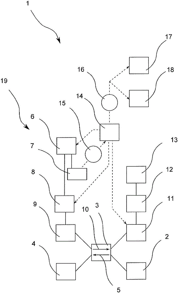
[0025] according to figure 1 , inside a compressed air system 1 of a motor vehicle (not shown further), a compression system 2 is connected on the output side to a dryer filter element 3 , which in turn is connected to a consumer system 4 .

[0026] In the operating state, the compression system 2 pumps possibly moist air in the operating direction 5 through the dryer filter 3 into the consumer system 4 , where it is dried until the dryer filter 3 is saturated.

[0027] In order to regenerate or dry the possibly saturated dryer insert 3 , in regeneration mode, dry air is conducted from the regeneration air reservoir 6 via the solenoid valve 8 and the non-return valve 9 into the dryer insert 3 . The dryer filter insert is then flowed through by drying gas in a regeneration direction 10 opposite to the running direction 5 , so that the regeneration or drying function of the dryer filter insert is carried out. The air flow is then discharged to the surroundings through outlet va...


PUM


Abstract

The invention relates to a method for identifying at least one fault in a regeneration path (19) of a pneumatic system (1) in a motor vehicle. Said method, in which air is conducted from a regeneration air reservoir (6) through a desiccant cartridge (3) in order to regenerate the desiccant cartridge (3), is characterized in that at least one physical parameter (15) of the air is acquired in a component of the regeneration path (19), the at least one physical parameter (15) is analyzed by an arithmetic unit (14) in order for a fault to be identified, and the result (16) of the analysis is further processed. The invention also relates to an associated device.

Description

technical field [0001] The invention relates to a method for detecting at least one fault in a regeneration path of a compressed air system of a motor vehicle, wherein air is guided through the dryer filter element from a regeneration air reservoir in order to regenerate the dryer filter element. Furthermore, the invention relates to a device for carrying out the method. [0002] A regeneration function is to be understood as an operating state in which a wet dryer filter element is dried by a dry air flow. The regeneration air reservoir is a compressed air reservoir from which dry air can be extracted, which is provided for passing through the regeneration path during regeneration against the usual air flow direction during operation. Dryer filter flow. [0003] The field of use of the invention extends to commercial vehicles with compressors. The air supplied by such compressors, which may contain liquid or aerosol particles in vapor form, is directed through elements suc...

Claims


Application Information

Patent Timeline
Patent Type & Authority Applications(China)
IPC IPC(8): B01D53/26B60T17/00F15B19/00F15B21/04F15B21/041F15B21/048
CPCB01D53/261B60T17/004F15B19/005F15B21/041F15B21/048F15B2211/857F15B2211/6306F15B2211/8636B01D53/0454B01D2258/06B01D2257/80B01D2259/4566B60T17/221
Inventor Z·博尔达奇G·维格
Owner KNORR BREMSE SYST FUER NUTZFAHRZEUGE GMBH
Why Eureka
Try Eureka