Medical guide wire

A technology for guide wires and medical supplies. It is applied in the direction of guide wires, medical science, coatings, etc. It can solve problems such as poor torque transmission, difficulty in adjusting angles, and insufficient support, and achieve optimal torque transmission and less damage to blood vessels. , the effect of stabilizing the supporting force

Active Publication Date: 2021-04-02
上海璞慧医疗器械有限公司
View PDF14 Cites 6 Cited by
  • Summary
  • Abstract
  • Description
  • Claims
  • Application Information

AI Technical Summary

Problems solved by technology

However, the existing guide wires are more likely to damage human organs or tissues such as the inner wall of blood vessels.
This is mainly because some existing medical guide wires have high hardness and insufficient softness at the head end, and it is difficult to adjust the angle when passing through tortuous human organs or tissues such as the inner wall of blood vessels, and cannot pass through tortuous human organs or tissues such as the inner wall of blood vessels smoothly. It is easy to scratch the tortuous human organs or tissues such as the inner wall of the blood vessel; the tip of the other part of the guide wire is too soft, the support force is not enough and the torque transmission ability is poor, and it cannot pass through the tortuous human organs or tissues such as the inner wall of the blood vessel

Method used


Image

  • Medical guide wire
  • Medical guide wire
  • Medical guide wire

Examples


Embodiment 1

[0058] Embodiment 1: A kind of guide wire

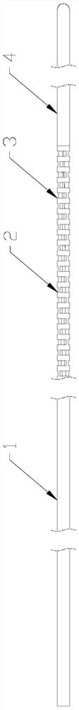
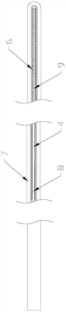
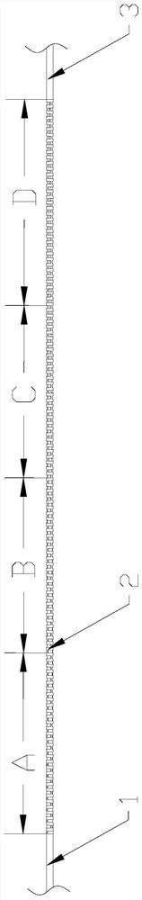
[0059] Such as Figure 1-5, the guide wire of the present invention is a guide wire, the guide wire comprises a near-end equal-diameter core wire segment 1 and a distal variable-diameter core wire segment 2; the variable-diameter core wire segment 1 comprises a proximal cutting segment 3 and the tip 4 at the distal end; several pairs of cut depressions 5 are evenly distributed in the axial direction on the cutting section 3, and the two depressions 5 of the same pair are arranged symmetrically about the axis of the variable-diameter core wire section 2, adjacent to each other. The two pairs of depressions 5 are alternately arranged.

[0060] Preferably, a spring 6 is sheathed on the tip 4 ; an elastic sheath 7 is wrapped around the spring 6 .

[0061] Preferably, the depth of the depression 5 gradually decreases from the proximal end to the distal end. There are several pairs of cut depressions uniformly distributed along the axia...

Embodiment 2

[0097] Embodiment 2: A kind of thrombectomy device

[0098] The thrombectomy device of the present invention contains the guide wire of Example 1.

Embodiment 3

[0099] Embodiment 3: A kind of fallopian tube unblocking device

[0100] The fallopian tube unblocking device of the present invention contains the guide wire of Example 1.


PUM

PropertyMeasurementUnit
lengthaaaaaaaaaa
diameteraaaaaaaaaa
lengthaaaaaaaaaa

Abstract

The invention discloses a medical guide wire, and belongs to the technical field of machinery. The invention provides a guide wire. The guide wire comprises a proximal isodiametric core wire section and a distal diameter-variable core wire section. The diameter-variable core wire section comprises a proximal cutting section and a distal tip. A plurality of pairs of recesses formed by cutting are uniformly distributed on the cutting section along the axial direction. The two recesses in the same pair are symmetrically arranged relative to the axis of the diameter-variable core wire section. Dueto every two adjacent pairs of recesses in staggered arrangement, the cutting section is set to enable the entire guide wire of the present invention to have stable support force and excellent torquetransmission capacity. Therefore the guide wire has the capacity of passing through tortuous blood vessels and is unlikely to injure blood vessels. According to the guide wire provided by the invention, a sharpened end is arranged on the tip of the guide wire, and a spring is sleeved on the the tip of the guide wire. An elastic sheath is wrapped outside the spring. Due to the arrangement of the tip and the elastic sheath, the optimal contact part between the guide wire and the inner walls of blood vessels is soft enough, so that the guide wire of the present invention is unlikely to injure the blood vessels.

Description

technical field [0001] The invention relates to a medical guide wire, which belongs to the technical field of machinery. Background technique [0002] Guide wire, also known as guide wire or guide wire, is one of the main tools for percutaneous catheterization. The guide wire guides and supports the catheter, helps the catheter enter blood vessels and other cavities, and guides the catheter to reach the lesion smoothly. In catheter therapy operations, it is as important as the catheter. [0003] Due to the operation involved in the body, the clinical requirements for the safety of the guide wire are very high. However, existing guide wires are all more likely to damage human organs or tissues such as blood vessel inner walls. This is mainly because some existing medical guide wires have high hardness and insufficient softness at the head end, and it is difficult to adjust the angle when passing through tortuous human organs or tissues such as the inner wall of blood vesse...

Claims


Application Information

Patent Timeline
Patent Type & Authority Applications(China)
IPC IPC(8): A61M25/09A61L31/02A61L31/10A61L31/04A61L31/06A61L31/14
CPCA61M25/09A61L31/022A61L31/10A61L31/048A61L31/06A61L31/14A61M2025/09133A61M2025/09175A61M2025/09183C08L39/06C08L27/18
Inventor 李涛田梦云陈万祺
Owner 上海璞慧医疗器械有限公司
Why Eureka
Try Eureka