Cable straightening equipment for municipal engineering

A cable and engineering technology, applied in the field of cable straightening equipment, can solve the problems of inability to clean cables and insufficient functionality, and achieve the effect of strong functionality, improved straightening effect, and not easy to shift

Inactive Publication Date: 2021-04-02
耿建军
View PDF0 Cites 6 Cited by
  • Summary
  • Abstract
  • Description
  • Claims
  • Application Information

AI Technical Summary

Problems solved by technology

[0009] The purpose of the present invention is to provide a cable straightening device used in municipal engineering to solve the problems in the above-mentioned background technology that the cable cannot be cleaned during the straightening process and the functionality is insufficient

Method used


Image

  • Cable straightening equipment for municipal engineering
  • Cable straightening equipment for municipal engineering
  • Cable straightening equipment for municipal engineering

Examples


Embodiment 1

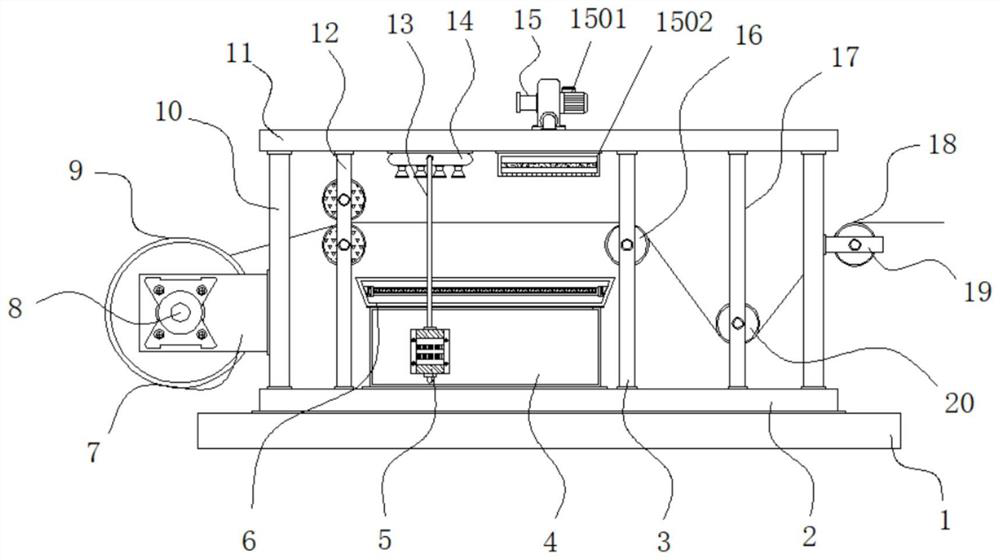
[0035] Example 1: See Figure 1-6, a cable straightening device for municipal engineering, comprising a base 1, a bottom plate 2, a pay-off roller 9 and a top plate 11, the bottom plate 2 is fixedly connected to the top of the base 1, and the two sides and two ends of the top of the bottom plate 2 are respectively fixed Connected with a support rod 10, the top plate 11 is fixedly connected to the top of the support rod 10, one side of the support rod 10 is fixedly connected with a fixed plate 7, the front end of the fixed plate 7 is fixedly connected with a drive motor 8, and the model of the drive motor 8 can be Y90L -4, the pay-off roller 9 is arranged between the fixed plates 7, the both sides of the pay-off roller 9 are provided with structures 21 for fixing, the side between the bottom plate 2 and the top plate 11 is provided with a limit guide structure 12, and the bottom of the top plate 11 A softening and drying mechanism 15 is provided at the middle position, and the ...

Embodiment 2

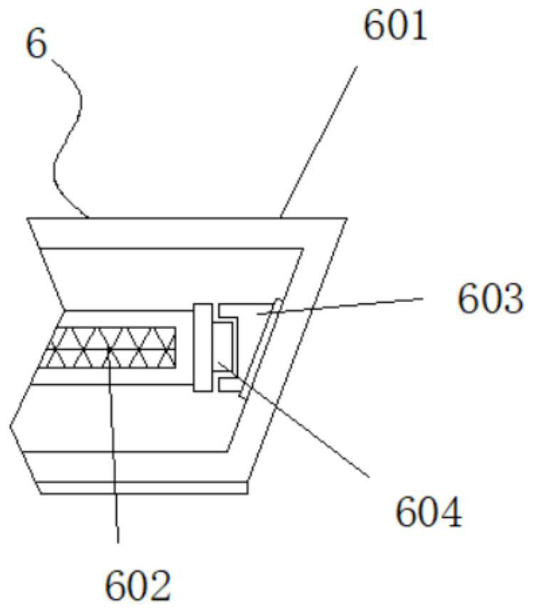
[0039] Embodiment 2: The water-saving structure 6 is composed of a water collection tank 601, a filter screen 602, a card slot 603 and a card block 604. The water collection tank 601 is fixedly connected to the top of the water tank 4, and both sides of the water collection tank 601 are respectively fixedly connected with card slots 603, the inside of the sump 601 is provided with a filter 602, and both sides of the filter 602 are respectively fixedly connected with blocks 604;

[0040] The outer diameter of the locking block 604 is smaller than the inner diameter of the locking slot 603, and an engaging structure is formed between the locking slot 603 and the locking block 604;

[0041] Specifically, such as figure 1 and image 3 As shown, when in use, the sewage generated by cleaning the cable will fall into the inside of the sump 601, and at this time, the filter screen 602 will filter the sewage, and then the clean water will flow into the inside of the water tank 4 again...

Embodiment 3

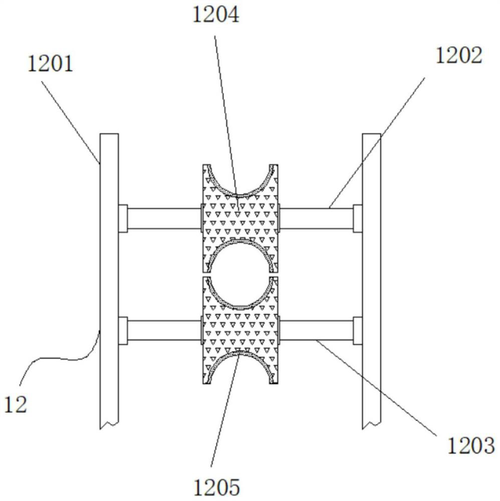
[0042] Embodiment 3: The limit guide structure 12 is composed of a vertical rod 1201, a first movable shaft 1202, a second movable shaft 1203, a limit guide roller 1204 and a protection pad 1205, and the vertical rod 1201 is respectively fixedly connected between the bottom plate 2 and the top plate 11 The first movable shaft 1202 is movably connected between the vertical rods 1201 at the position near the top, the bottom end of the first movable shaft 1202 is provided with a second movable shaft 1203, and the second movable shaft 1203 is connected to the vertical rod 1201 is movably connected, and the outsides of the middle positions of the first movable shaft 1202 and the second movable shaft 1203 are respectively fixedly connected with the limit guide roller 1204, and the inside of the limit guide roller 1204 is provided with a protective pad 1205;

[0043] A semicircular groove is arranged inside the outer end of the limit guide roller 1204;

[0044] Specifically, such as ...


PUM


Abstract

The invention discloses cable straightening equipment for municipal engineering, and particularly relates to the technical field of municipal engineering. The cable straightening equipment comprises abase, a bottom plate, a pay-off roller and a top plate, the bottom plate is fixedly connected to the top end of the base, supporting rods are fixedly connected to the two sides and the two ends of the top of the bottom plate correspondingly, the top plate is fixedly connected to the top ends of the supporting rods, and a fixing plate is fixedly connected to one sides of the supporting rods. By arranging a fan, a heating box, an air outlet and an electric heating wire, when the cable straightening equipment is used, after a cable is cleaned, the electric heating wire is powered on, the fan isstarted, the fan can blow air into the heating box, the electric heating wire can heat the air, and finally the air is exhausted through the air outlet, so that the cleaned cable can be dried and softened, the softened cable can easily pass through the top end of a first straightening roller, the bottom end of a second straightening roller and the top end of a wire outlet roller in sequence to bestraightened, and the straightening effect of the cable is greatly improved.

Description

technical field [0001] The invention relates to the technical field of municipal engineering, in particular to a cable straightening device for municipal engineering. Background technique [0002] The cables used in the municipal engineering construction process are usually in a coiled state before use. Since they are in a coiled state for a long time, in order to save cables during use, the cables need to be straightened. A cable straightening device for municipal engineering is also needed in the construction process of municipal engineering, but there are many problems and defects in the existing cable straightening equipment for municipal engineering. [0003] In the process of realizing the present invention, the inventors have found that at least the following problems in the prior art have not been resolved: [0004] (1) The traditional cable straightening equipment used in municipal engineering cannot clean the cable during the straightening process, and its functio...

Claims


Application Information

Patent Timeline
Patent Type & Authority Applications(China)
IPC IPC(8): B65H49/24B65H49/36B65H57/14B65H57/06B65H57/26B08B3/02F26B13/08F26B13/12F26B21/00
CPCB08B3/022B65H49/24B65H49/36B65H57/06B65H57/14B65H57/26B65H2701/34F26B13/08F26B13/12F26B21/001F26B21/004
Inventor 耿建军
Owner 耿建军
Why Eureka
Try Eureka