
Synchronous belt tensioning device

A technology of tensioning device and synchronous belt, which is applied in the direction of transmission device, belt/chain/gear, mechanical equipment, etc. It can solve the problems of low work efficiency and inability to ensure that the tension meets the requirements.

Active Publication Date: 2021-04-02
SHENZHEN YUEJIANG TECH CO LTD
View PDF8 Cites 0 Cited by
  • Summary
  • Abstract
  • Description
  • Claims
  • Application Information

AI Technical Summary

Problems solved by technology

[0005] The main purpose of the present invention is to propose a synchronous belt tensioning device, aiming to solve the problem that the current synchronous belt tensioning method has low working efficiency and cannot ensure that the tension meets the Asked technical questions

Method used


Image

  • Synchronous belt tensioning device
  • Synchronous belt tensioning device
  • Synchronous belt tensioning device

Examples


Embodiment Construction

[0021] The solutions in the embodiments of the present invention will be clearly and completely described below in conjunction with the accompanying drawings in the embodiments of the present invention. Apparently, the described embodiments are only some of the embodiments of the present invention, not all of them. Based on the embodiments of the present invention, all other embodiments obtained by persons of ordinary skill in the art without creative efforts fall within the protection scope of the present invention.

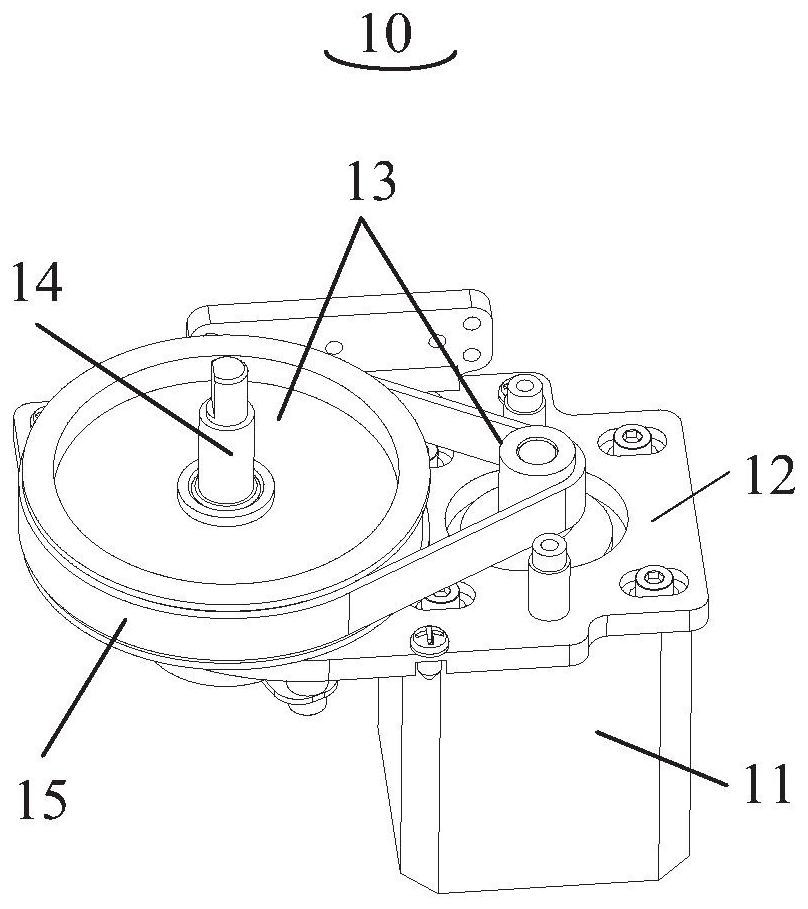
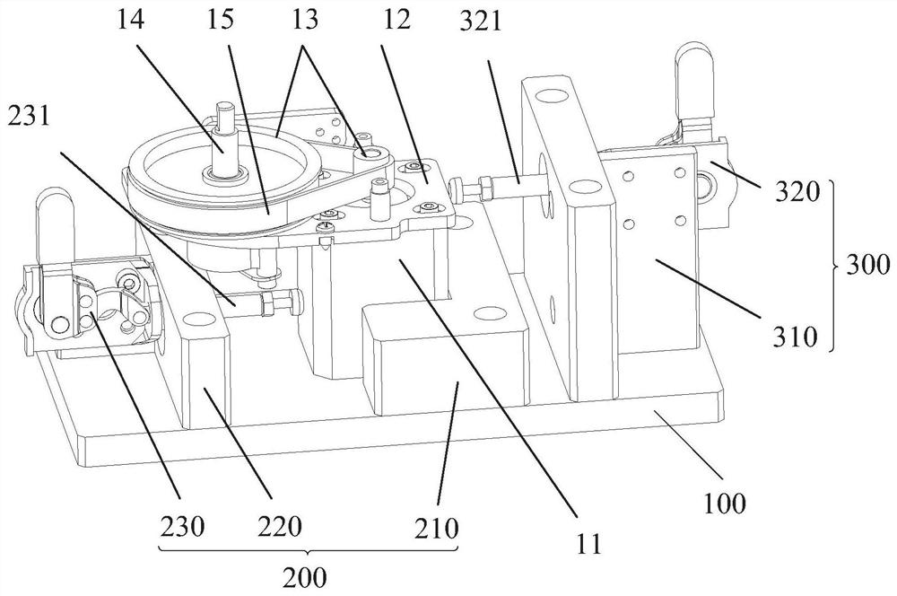
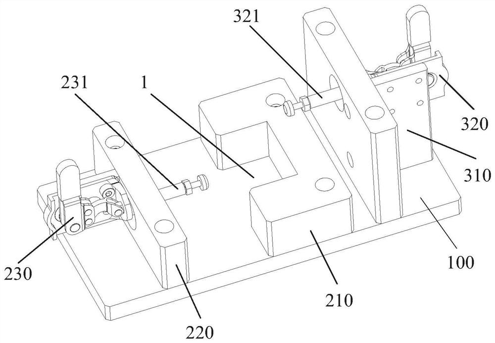
[0022] The present invention proposes a synchronous belt tensioning device, which is applied to the synchronous drive assembly 10, referring to Figure 1 to Figure 3 , the synchronous drive assembly 10 includes a motor 11 and a fixed plate 12 arranged at the output end of the motor 11, the fixed plate 12 is provided with a rotating shaft 14 for installing a pulley 13, wherein the synchronous belt tensioning device includes a mounting plate 100 and is arranged on ...


PUM


Abstract

The invention discloses a synchronous belt tensioning device. The device is applied to a synchronous driving assembly, the synchronous driving assembly comprises a motor and a fixing plate arranged atthe output end of the motor, and a rotating shaft used for installing a belt wheel is arranged on the fixing plate. The synchronous belt tensioning device comprises a mounting plate, a positioning assembly and a pushing assembly, the positioning assembly and the pushing assembly are arranged on the mounting plate, the positioning assembly is used for fixing the motor, and the pushing assembly isused for pushing the fixing plate arranged on the motor to move. The synchronous belt tensioning device is a special tool designed for a synchronous belt driving assembly, can be used for conducting synchronous belt tensioning operation on batch synchronous belt driving assemblies, is high in working efficiency and can ensure that the tensioning force of the synchronous belt meets the requirement.

Description

technical field [0001] The invention relates to the technical field of synchronous belts, in particular to a synchronous belt tensioning device. Background technique [0002] In industrial production, in order to realize the work and operation of most mechanical equipment, it is generally configured with a motor as a power source and a synchronous drive component driven by a synchronous belt, such as a collaborative robot, a belt conveyor, etc. Specifically, such as figure 1 As shown, the synchronous drive assembly is mainly composed of a fixed plate, a motor, a rotating shaft, two pulleys respectively fixed on the rotating shaft and the output shaft of the motor, and a timing belt set on the two pulleys, wherein the motor and the rotating shaft are located on the fixed plate The fixed plate is provided with an opening through which the output shaft of the power supply passes. The body of the motor and the fixed plate are provided with mounting holes correspondingly, and sc...

Claims


Application Information

Patent Timeline
IPC IPC(8): F16H7/14F16H7/02
CPCF16H7/14F16H7/02
Inventor 甘海宏刘主福叶伟智
Owner SHENZHEN YUEJIANG TECH CO LTD
Learn More