Processing equipment for crimping insulating film on electronic lead
A technology of insulating film and processing equipment, applied in the direction of transformer/inductor coil/winding/connection, transformer/inductor parts, inductor/transformer/magnet manufacturing, etc., which can solve the problem of low safety factor and poor versatility, etc. problems, to achieve the effect of improving the safety factor, solving the poor versatility, and improving the effect of crimping
- Summary
- Abstract
- Description
- Claims
- Application Information
AI Technical Summary
Problems solved by technology
Method used
Image

Examples
Embodiment 1
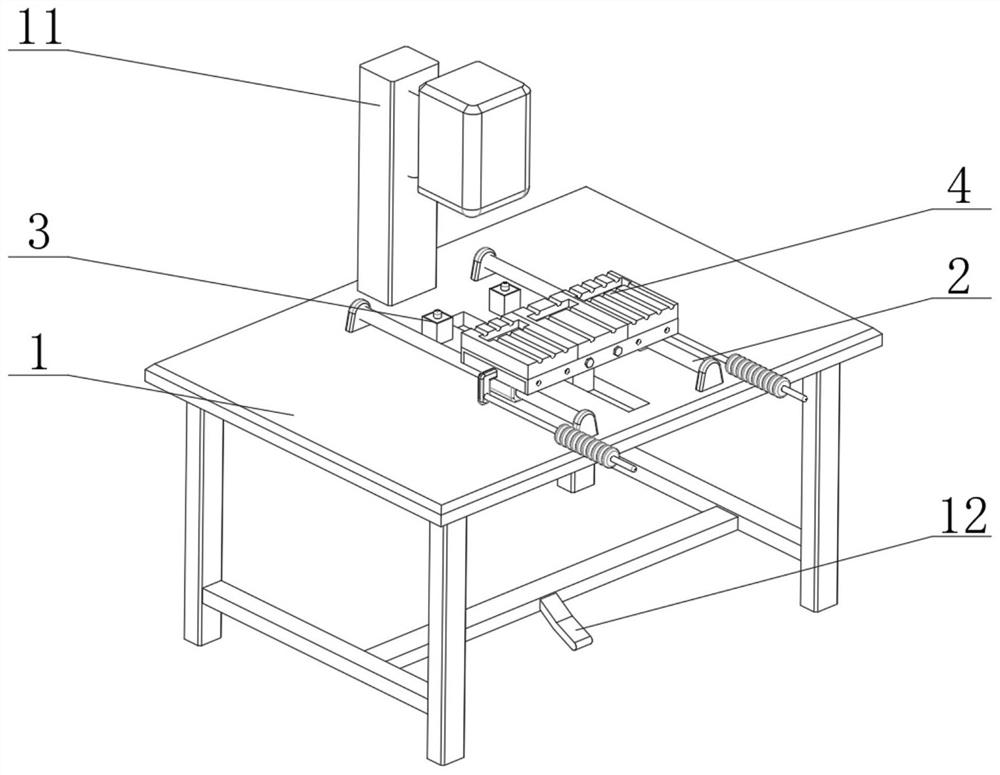
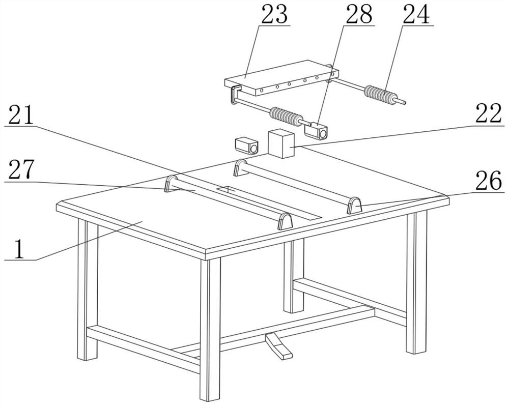
[0031] see figure 1 and 2 , a processing device for crimping insulating films on electronic leads, comprising a workbench 1, a high-frequency machine pressing die 11 and a control pedal 12, a sliding mechanism 2 is provided in the middle of the top of the workbench 1, and the sliding mechanism 2 includes a sliding track 21. The main slider 22, the bearing plate 23 and two sliding handrails 24, the sliding track 21 is set in the middle of the top of the workbench 1, the main slider 22 is slidably connected to the inside of the sliding track 21, and the bearing plate 23 is fixedly connected to the bearing plate 23, two sliding handrails 24 are fixedly connected to the both sides of the load plate 23, both sides of the sliding track 21 are provided with limiting guide rails 27, and the two ends of the limiting guide rails 27 are fixedly connected with auxiliary brackets 26, auxiliary brackets 26 The bottom of the bearing plate 23 is fixedly connected with the workbench 1, and th...
Embodiment 2
[0034] see figure 1 , 4 and 5, the present embodiment is further optimized on the basis of embodiment 1, specifically, two positioning mechanisms 3 are provided between the carrying plate 23 and the workbench 1, and the positioning mechanisms 3 include a positioning box 31, a pressure Spring 32, top plate 33, round head positioning pin 34 and positioning groove 36, positioning box 31 are fixedly connected on the top of workbench 1, pressure spring 32, top plate 33 and round head positioning pin 34 are all positioned at the inside of positioning box 31, The positioning slot 36 is defined at the bottom of the supporting board 23 .
[0035] Specifically, the top plate 33 is slidably connected to the positioning box body 31 , and the pressure spring 32 is fixedly connected between the top plate 33 and the inner cavity bottom of the positioning box body 31 .
[0036] Specifically, a packaging board 35 is fixedly connected to the top of the positioning box 31 .
[0037] Specifica...
Embodiment 3
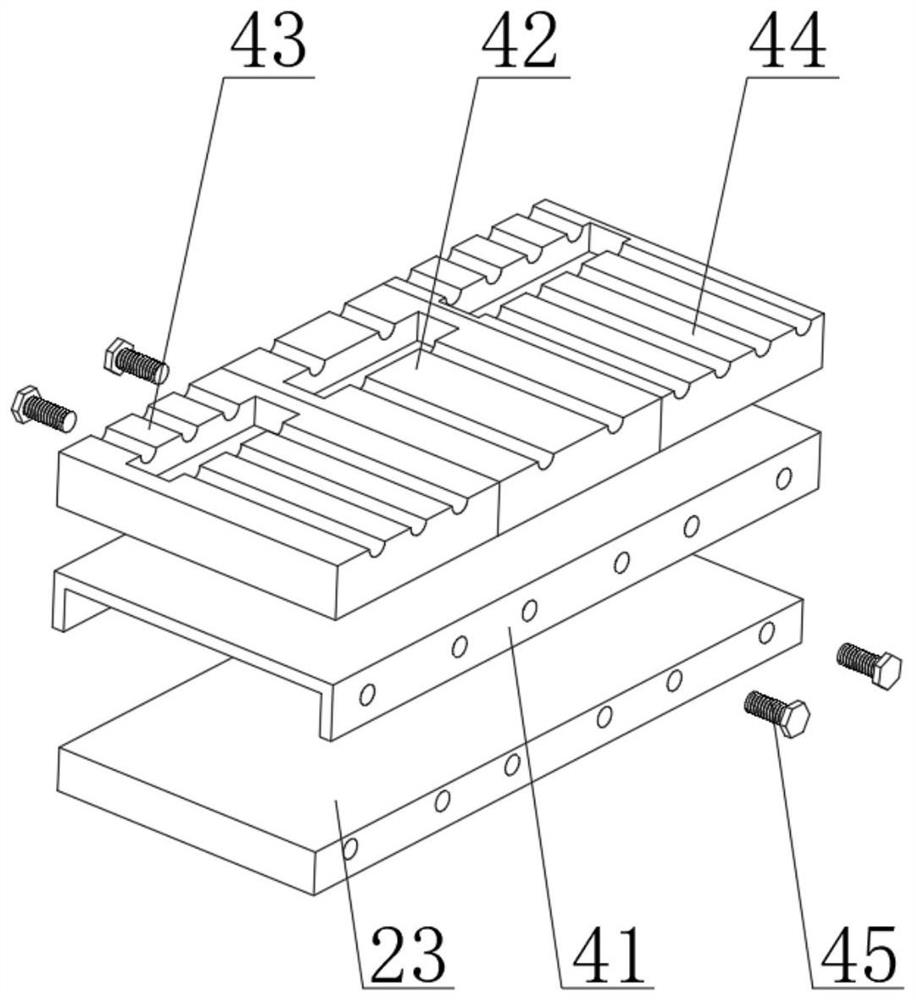
[0040] see figure 1 and 3 , the present embodiment is optimized as follows on the basis of example 1 or example 2, specifically, the top of the carrying plate 23 is provided with a quick release module 4, and the quick release module 4 includes a module mounting plate 41, a double wire mold Group 42, three-wire module 43, four-wire module 44 and two fixing screws 45, two-wire module 42, three-wire module 43 and four-wire module 44 are all fixedly connected to the top of module mounting plate 41.
[0041] Specifically, the module mounting plate 41 is slidably connected to the carrying plate 23 , and the fixing screws 45 pass through the module mounting plate 41 and are screwed to the carrying plate 23 .
[0042] Specifically, the two-wire module 42 is fixedly connected to the top middle of the module mounting plate 41 , and the three-wire module 43 and the four-wire module 44 are respectively located on both sides of the two-wire module 42 .
[0043] In this embodiment, a two-w...
PUM
 Abstract
Description
Claims
Application Information
 - R&D Engineer
- R&D Manager
- IP Professional
- Industry Leading Data Capabilities
- Powerful AI technology
- Patent DNA Extraction
Browse by: Latest US Patents, China's latest patents, Technical Efficacy Thesaurus, Application Domain, Technology Topic.
© 2024 PatSnap. All rights reserved.Legal|Privacy policy|Modern Slavery Act Transparency Statement|Sitemap