Non-contact variable capacitor-loaded frequency-tunable microstrip patch antenna

A technology of microstrip patch antenna and microstrip patch, which is applied in the direction of antenna, antenna grounding switch structure connection, electrical components, etc., can solve the problem that the radiation performance is greatly affected, achieve continuous tuning, increase the degree of freedom, and reduce the impact Effect

Active Publication Date: 2021-04-02
NANTONG UNIVERSITY
View PDF7 Cites 1 Cited by
  • Summary
  • Abstract
  • Description
  • Claims
  • Application Information

AI Technical Summary

Problems solved by technology

[0004] However, in the above designs, the tunable structure is directly connected to the radiation patch, which makes the variable capacitance have a greater impact on the radiation performance of the resonator. Therefore, the present invention proposes a new non-contact variable capacitance loading scheme for the first time. To design a frequency reconfigurable antenna working in the main mode TM10 mode, compared with the traditional frequency reconfigurable microstrip patch antenna, the non-contact variable capacitive loading scheme separates the radiating patch from the tunable structure To reduce the impact of loading the tunable structure on the antenna radiation performance and improve the degree of freedom of design

Method used


Image

  • Non-contact variable capacitor-loaded frequency-tunable microstrip patch antenna
  • Non-contact variable capacitor-loaded frequency-tunable microstrip patch antenna
  • Non-contact variable capacitor-loaded frequency-tunable microstrip patch antenna

Examples


Embodiment Construction

[0017] The present invention will be further described below in conjunction with the accompanying drawings and specific embodiments.

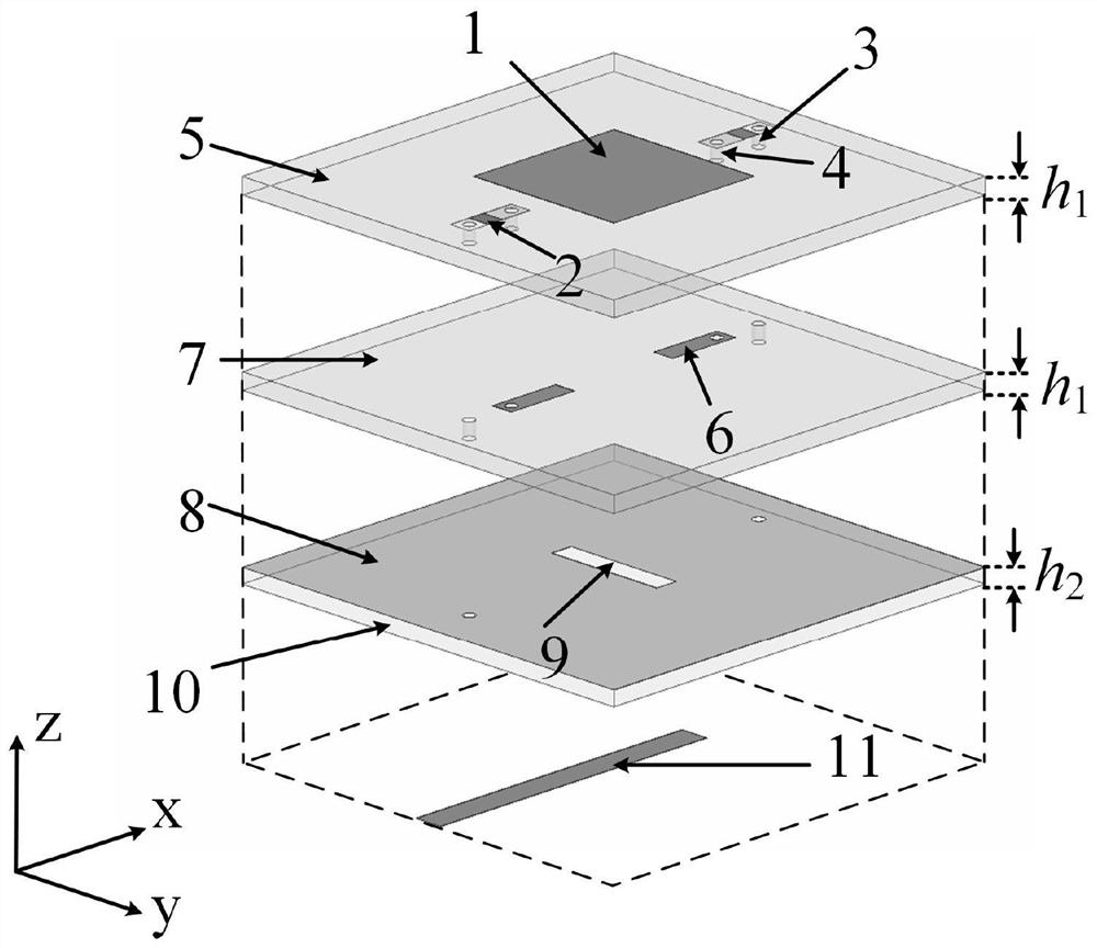
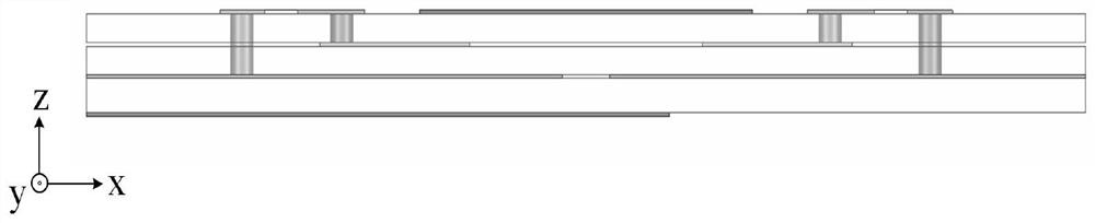
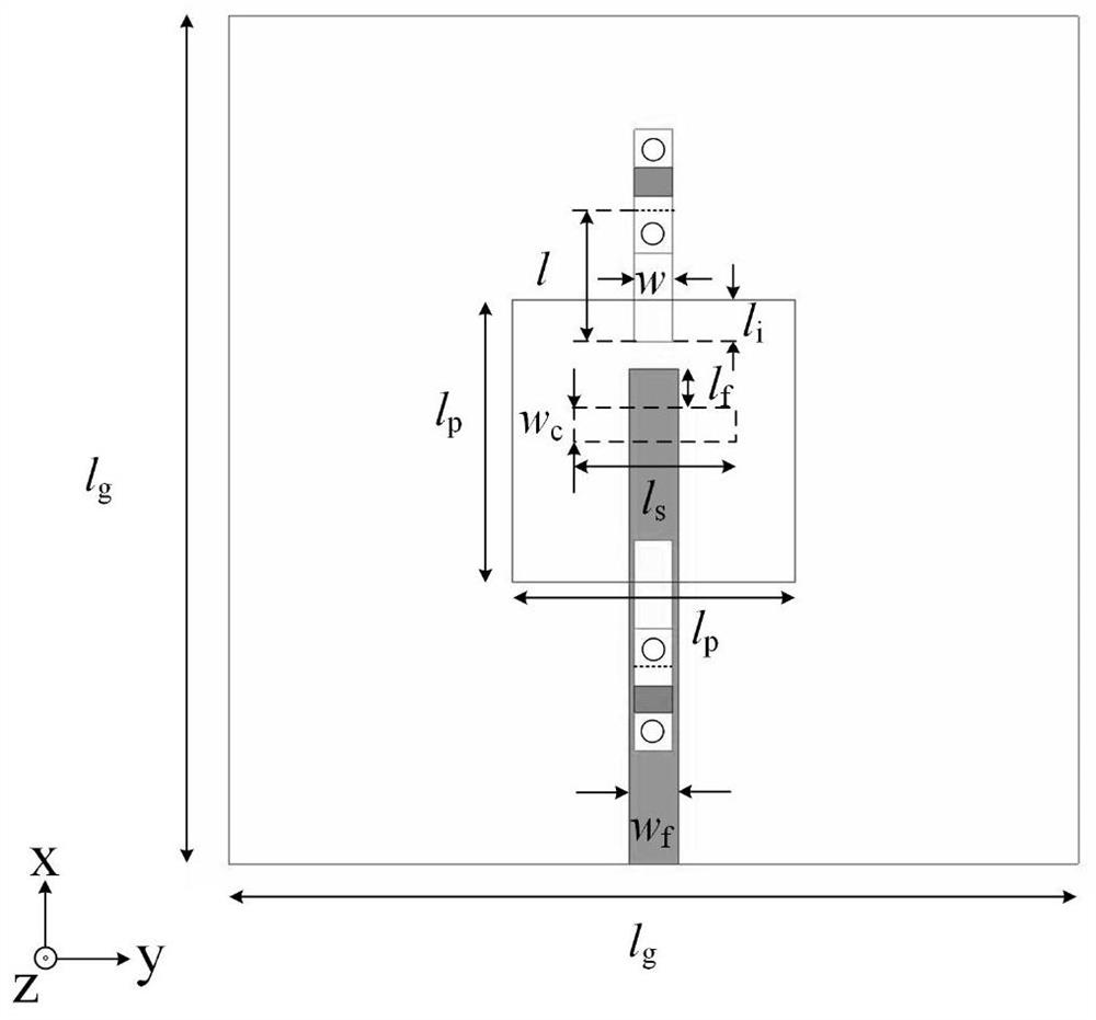
[0018] Such as Figure 1 to Figure 3 As shown, the frequency-tunable microstrip antenna loaded with non-contact variable capacitance in this embodiment includes a bottom substrate 10 and a microstrip patch resonator. The microstrip patch resonator includes a metal reflective floor 8 , an intermediate substrate 7 , a top substrate 5 and a microstrip patch 1 stacked in sequence from bottom to top. The microstrip patch 1 is a rectangular microstrip patch, and is disposed in the center of the top substrate 5 . There is a pair of microstrip lines 6 for frequency tuning between the top substrate 5 and the middle substrate 7 , and the microstrip lines 6 for frequency tuning are arranged along the centerline of the microstrip patch 1 and arranged symmetrically with respect to the microstrip patch. The microstrip line 6 for frequency tuning overlaps t...


PUM

PropertyMeasurementUnit
dielectric lossaaaaaaaaaa

Abstract

The invention relates to a non-contact variable capacitor-loaded frequency-tunable microstrip patch antenna. The microstrip patch antenna comprises a bottom substrate, a microstrip patch resonator anda microstrip feeder line, wherein the microstrip patch resonator and the microstrip feeder line are arranged on the upper surface and the lower surface of the bottom substrate respectively; the microstrip patch resonator comprises a metal reflection floor, a middle substrate, a top substrate and microstrip patches which are sequentially stacked from bottom to top; a pair of microstrip lines for frequency tuning is arranged between the middle substrate and the top substrate; the microstrip lines for frequency tuning are overlapped with the microstrip patches in a non-contact mode across the top substrate; and the outer ends of the microstrip lines for frequency tuning are electrically connected with the inner ends of variable capacitors loaded on the upper surface of the top substrate, andthe outer ends of the variable capacitors are grounded. The microstrip lines for frequency tuning and the corresponding variable capacitors form a non-contact frequency tuning structure which is usedfor continuously tuning the frequency of the antenna. The invention provides a novel non-contact variable capacitor loading scheme for the first time to design the frequency-reconfigurable microstrippatch antenna working under the main mode TM10.

Description

technical field [0001] The invention relates to the technical field of wireless communication, in particular to a frequency-tunable microstrip patch antenna loaded with a non-contact variable capacitance. Background technique [0002] In order to meet the development requirements of wireless communication systems, multifunctional antennas have been extensively studied in recent years. Among them, the excellent performance of reconfigurable antennas has become a research hotspot. Reconfigurable antennas have excellent characteristics such as small size and flexible functions, and can replace multiple antennas. The reconfigurable resonator is the core unit of the reconfigurable antenna, which directly affects the performance of the reconfigurable antenna. In recent years, people's research on reconfigurable resonators mainly focuses on the operating frequency, radiation pattern, and polarization, and they play an important role in modern wireless communication systems. Amon...

Claims


Application Information

Patent Timeline
Patent Type & Authority Applications(China)
IPC IPC(8): H01Q1/38H01Q1/50H01Q13/08
CPCH01Q1/38H01Q13/08H01Q1/50
Inventor 陈建新张小珂王雪颖唐世昌杨玲玲
Owner NANTONG UNIVERSITY
Why Eureka
Try Eureka