
Rotor of miniature permanent magnet motor

A permanent magnet motor and rotor technology, applied in the direction of magnetic circuit rotating parts, magnetic circuits, electrical components, etc., can solve the problems of reduced fatigue resistance of permanent magnets, poor stability of permanent magnets, and reduced service life of motors, etc., to achieve Increase the effect of fixing, simple structure and prolonging the service life

Active Publication Date: 2021-04-02
超音速智能技术(杭州)有限公司
View PDF9 Cites 0 Cited by
  • Summary
  • Abstract
  • Description
  • Claims
  • Application Information

AI Technical Summary

Problems solved by technology

[0004] However, the permanent magnets in the rotors of micro permanent magnet motors currently on the market are usually bonded to the outer circumference of the rotor yoke with high-temperature glue, or the permanent magnets are embedded on the outer circumference of the rotor yoke. When the torque increases, the The greater the shear force, the lower the fatigue resistance of the permanent magnet as a component, and the greater the possibility of damage. The stability of the permanent magnet is not good. service life

Method used


Image

  • Rotor of miniature permanent magnet motor
  • Rotor of miniature permanent magnet motor
  • Rotor of miniature permanent magnet motor

Examples


Embodiment Construction

[0031] The following will clearly and completely describe the technical solutions in the embodiments of the present invention with reference to the accompanying drawings in the embodiments of the present invention. Obviously, the described embodiments are only some, not all, embodiments of the present invention. Based on the embodiments of the present invention, all other embodiments obtained by persons of ordinary skill in the art without making creative efforts belong to the protection scope of the present invention.

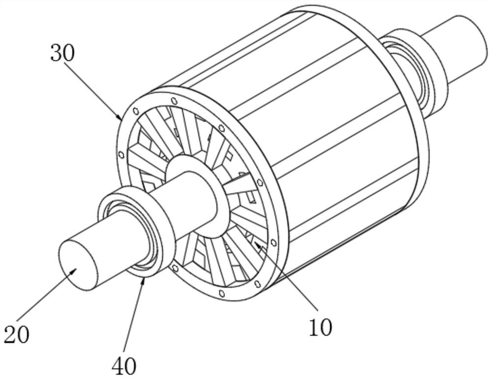
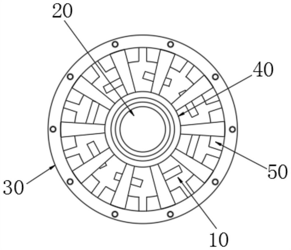
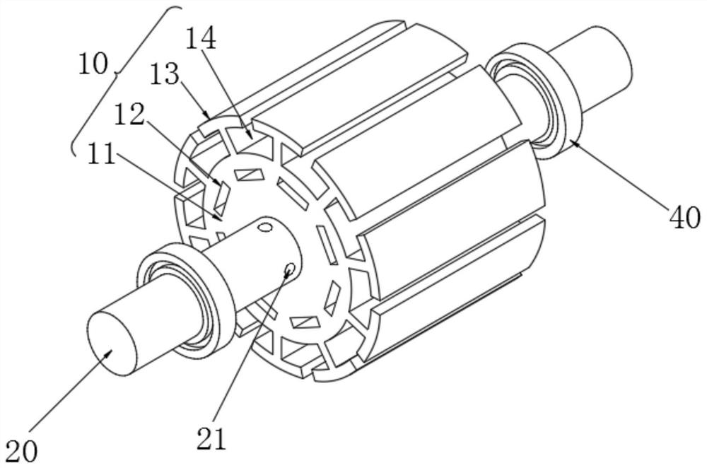
[0032] see Figure 1-10 , in an embodiment of the present invention, a rotor of a miniature permanent magnet motor includes a rotor body 10, a rotating shaft 20 is embedded in the center of the rotor body 10, and a permanent magnet block 50 is arranged inside the rotor body 10, and the rotor body 10 The outer side of the sleeve is provided with a fixed mount 30, the fixed mount 30 is used to fix the permanent magnet block 50, and the two ends of the rotating s...


PUM


Abstract

The invention discloses a rotor of a miniature permanent magnet motor, and relates to the technical field of motors. The motor comprises a rotor body, wherein a rotating shaft is embedded in the central position of the rotor body, a permanent magnet block is arranged on the inner side of the rotor body, a fixing frame is sleeved on the outer side of the rotor body, and is used for fixing the permanent magnet block, and bearings are arranged at the two ends of the rotating shaft in a sleeving mode. According to the invention, the rotor is reasonable in structure, convenient to mount and dismount and good in stability; the permanent magnet block can be fixed in the rotor core through the arranged fixing frame, so that the stability is improved, and the permanent magnet block cannot be disengaged when the motor rotates at a high speed; and the fixing frame can be quickly mounted and dismounted, so that the permanent magnet block can be conveniently replaced, the subsequent maintenance processing of the rotor is convenient, the problems of poor stability and easy shedding of the permanent magnet blocks bonded on the rotor yoke in the existing permanent magnet motor rotor are solved, the service life of the motor rotor is prolonged, and the production cost is reduced.

Description

technical field [0001] The invention relates to the technical field of motors, in particular to a rotor of a miniature permanent magnet motor. Background technique [0002] The permanent magnet brushless DC motor is a DC motor with a magnetic field established by one or more permanent magnets. Its performance is similar to that of a separately excited DC motor with constant excitation current, and the speed can be easily adjusted by changing the armature voltage. Compared with other DC motors, it has the advantages of small size, high efficiency, simple structure, and less copper consumption. It is the main type of low-power DC motors. [0003] A permanent magnet motor is mainly composed of a stator, a rotor, and an end cover. The rotor refers to a rotating body supported by a bearing, and is mainly composed of a rotor core, a permanent magnet, and a rotating shaft. [0004] However, the permanent magnets in the rotors of micro permanent magnet motors currently on the marke...

Claims


Application Information

Patent Timeline
IPC IPC(8): H02K1/30H02K1/27
CPCH02K1/30H02K1/278
Inventor 张磊张伟
Owner 超音速智能技术(杭州)有限公司
Learn More