
Multi-motor control circuit of thermal infrared imager

A multi-motor control, infrared thermal imager technology, applied in the field of infrared detection, can solve the problem that the drive control circuit cannot be compatible with multiple motors at the same time, etc.

Pending Publication Date: 2021-04-02
11TH RES INST OF CHINA ELECTRONICS TECH GROUP CORP
View PDF0 Cites 2 Cited by
  • Summary
  • Abstract
  • Description
  • Claims
  • Application Information

AI Technical Summary

Problems solved by technology

[0004] The invention provides a multi-motor control circuit for an infrared thermal imager to solve the problem that the existing drive control circuit cannot be compatible with multiple motors at the same time

Method used


Image

  • Multi-motor control circuit of thermal infrared imager
  • Multi-motor control circuit of thermal infrared imager
  • Multi-motor control circuit of thermal infrared imager

Examples


Embodiment Construction

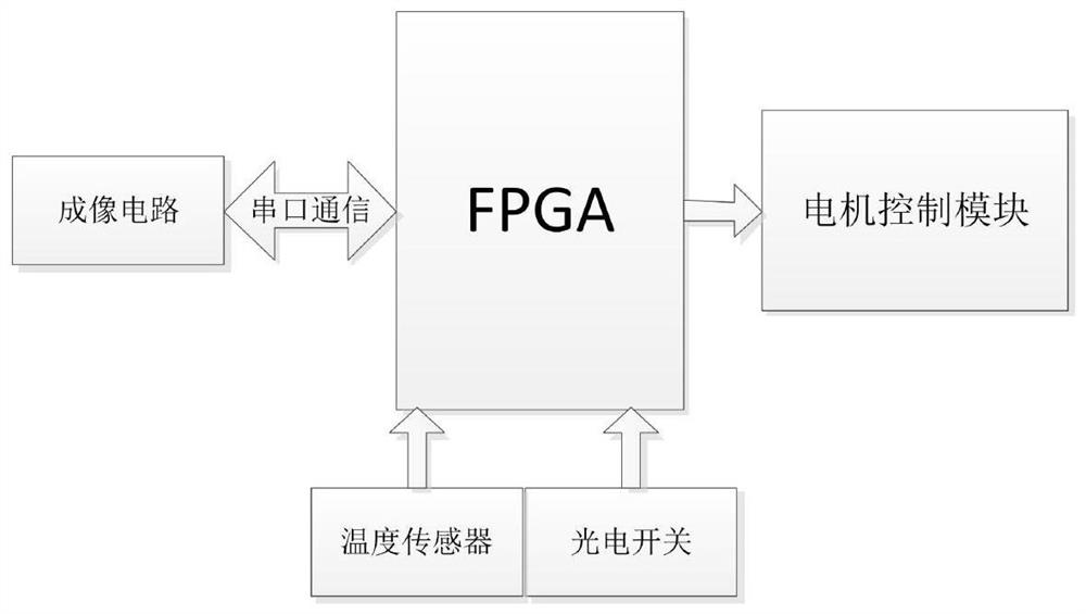
[0030] The hardware circuit in the existing infrared thermal imager uses PPGA as the processor imaging circuit as the core, and the motor control generally uses ARM and MCU as the processing core. It is necessary to unify the processor type to reduce the types of software and hardware development and save development resources. At the same time, in order to realize continuous zooming, the circuit must be realized by cooperation of multiple motors, and a special motor drive circuit needs to be designed. In addition, the types of motors in the infrared thermal imager are divided into focusing motors and field of view motors according to the functions of the motors. Generally, the stepping motor is used to realize the focusing function, and the DC motor is used to realize the field of view switching function. The number and position of stepper motors and DC motors are designed according to the needs of the thermal imager, so the drive control circuit that meets the needs of variou...


PUM


Abstract

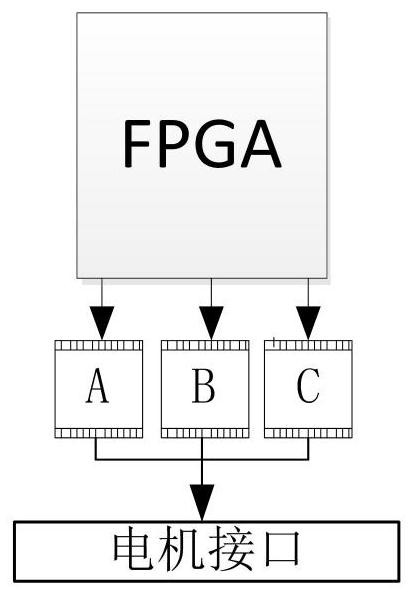
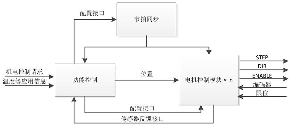
The invention discloses a multi-motor control circuit of a thermal infrared imager. The multi-motor control circuit is applied to a multi-type thermal infrared imager, can complete the control of eachmotor of the thermal infrared imager and is matched with a motor control software program; and the multi-motor control circuit, a related motor, a mechanical structure, a photoelectric switch and thelike are cooperatively matched and controlled. By means of the above design, multi-motor cooperative control with time precision reaching the levelo f 0.01 microsecond and position precision reachingthe level of 0.01 millimeter can be completed; the functions of the multi-motor control circuit are diversified; a unified motor interface is adopted, so subsequent updating and maintenance are facilitated; and the design has important significance in research of a continuous zoom system and motor control.

Description

technical field [0001] The invention relates to the technical field of infrared detection, in particular to a multi-motor control circuit for an infrared thermal imager. Background technique [0002] In recent years, with the development of infrared imaging technology, infrared zoom system has been widely used in surveillance, infrared forward-looking and target recognition and other fields. Compared with the traditional zoom system, the continuous zoom system can realize the conversion between the search and tracking field of view without sudden changes, and can keep the image plane position stable during the field of view conversion process, and can better achieve fast and accurate tracking and measurement targets. [0003] In the field of infrared thermal imaging cameras, the hardware circuit uses PPGA as the processor imaging circuit as the core, and the motor control generally uses ARM and MCU as the processing core. It is necessary to unify the processor type to reduc...

Claims


Application Information

Patent Timeline
IPC IPC(8): H02P5/00H02P5/60H02P8/40
CPCH02P5/00H02P5/60H02P8/40
Inventor 刘梁然刘纪洲青鸿阅许静
Owner 11TH RES INST OF CHINA ELECTRONICS TECH GROUP CORP
Learn More