A positioning device for circuit board drilling
A positioning device and circuit board technology, applied in the direction of circuit board tool positioning, printed circuit, printed circuit manufacturing, etc.
- Summary
- Abstract
- Description
- Claims
- Application Information
AI Technical Summary
Problems solved by technology
Method used
Image

Examples
Embodiment 1
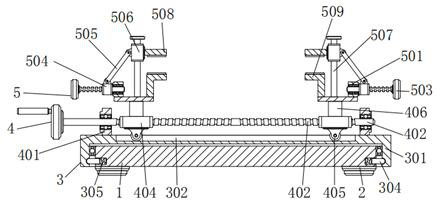
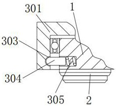
[0031] A positioning device for circuit board drilling, comprising a base plate 1, the bottom four corners of the base plate 1 are fixedly connected with a base 2, the top of the base plate 1 is provided with a rotating mechanism 3, the rotating mechanism 3 includes a groove frame 301, a chute 302, an arc Shaped card slot 303, arc bar 304 and spring 305, groove frame 301 is arranged on the outer wall of bottom plate 1, and the top of groove frame 301 is processed with chute 302, and the inner wall of groove frame 301 and the outer wall of bottom plate 1 clearance fit , the inner wall of the groove frame 301 is rotationally connected with the outer wall of the bottom plate 1 through bearings, so that the groove frame 301 can rotate on the outer wall of the bottom plate 1, and the inner wall of the groove frame 301 is processed with a plurality of arc-shaped slots 303, the left and right sides The inner walls of the arc-shaped slots 303 are all clamped with arc-shaped clamping ro...
Embodiment 2
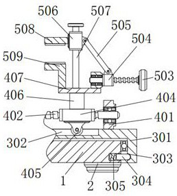
[0033] As an option, see figure 1 , 2 , 4, 5 and 6, the circuit board drilling positioning device, the top of the groove frame 301 is provided with an adjustment mechanism 4, the adjustment mechanism 4 includes a first support seat 401, a double-ended screw 402, a rotating disk 403, a first sleeve 404 , a pulley 405, a vertical bar 406 and a horizontal plate 407, two first support seats 401 are respectively located on the left and right sides of the outer wall top of the groove frame 301, and the outer wall bottoms of the two first support seats 401 are respectively connected to the groove frame 301. The left and right sides of the top of the outer wall are fixed together, and the inner walls of the two first support seats 401 are connected with a double-ended screw 402 through bearing rotation, so that the double-ended screw 402 can rotate on the inner wall of the first support seat 401, and the double-ended screw 402 A turntable 403 is fixed on the left side of the outer wa...
Embodiment 3
[0036] As an option, see figure 1 , 2And 6, the positioning device for circuit board drilling, the tops of the two horizontal plates 407 are all provided with a positioning mechanism 5, and the positioning mechanism 5 includes a second support seat 501, a screw rod 502, a handle 503, a second sleeve 504, a rod body 505, Sliding sleeve 506, slide bar 507, plate body 508 and curved plate 509, two second support seats 501 are respectively arranged on the outer wall tops of two horizontal plates 407, and the inner wall of the second support seat 501 is provided with screw rod 502, and the screw rod 502 The outer wall is rotatably connected with the inner wall of the second support base 501 through the bearing, so that the screw rod 502 can rotate on the inner wall of the second support base 501. A handle 503 is fixedly connected to the outside of the screw rod 502, and the handle 503 is used to drive the screw rod 502 to rotate. The outer wall of 502 is provided with the second s...
PUM
 Abstract
Description
Claims
Application Information
 - R&D
- Intellectual Property
- Life Sciences
- Materials
- Tech Scout
- Unparalleled Data Quality
- Higher Quality Content
- 60% Fewer Hallucinations
Browse by: Latest US Patents, China's latest patents, Technical Efficacy Thesaurus, Application Domain, Technology Topic, Popular Technical Reports.
© 2025 PatSnap. All rights reserved.Legal|Privacy policy|Modern Slavery Act Transparency Statement|Sitemap|About US| Contact US: help@patsnap.com