

Multifunctional adjusting device of swivel chair chassis and using method thereof
An adjustment device and multi-functional technology, applied to chairs, chairs, recliners and other directions that can adjust the seat vertically, can solve the problems of insufficient elastic force, large elastic force, and inability to quickly adjust spring hardness, etc., to achieve large elastic force and elastic force Large, quick adjustment effect
- Summary
- Abstract
- Description
- Claims
- Application Information
AI Technical Summary
Problems solved by technology
Method used
Image

Examples
Embodiment 1
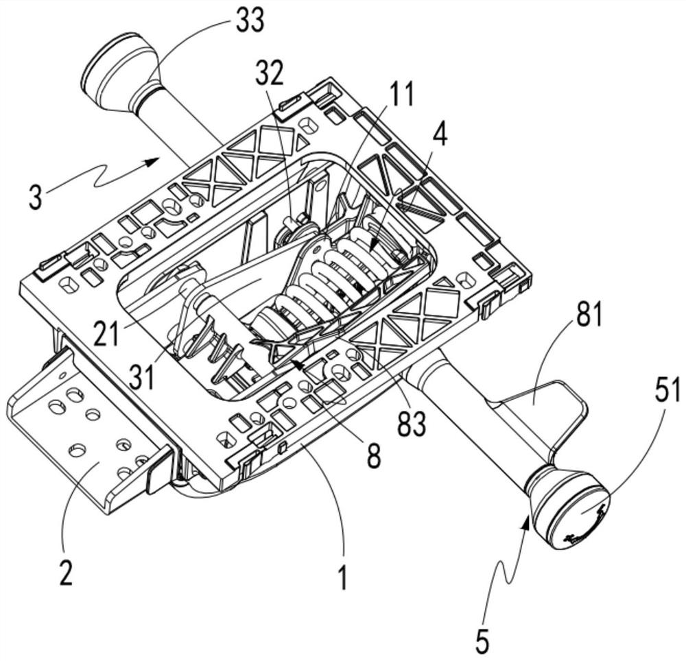
[0052] Such as Figures 1 to 3 As shown, a multifunctional adjustment device for a swivel chair chassis includes a housing 1 and a backrest mounting plate 2, the backrest mounting plate 2 is hinged on the housing 1 through a kingpin shaft 21, and the backrest mounting plate 2 is A jacking shaft 22 parallel to the kingpin shaft 21 is provided, and an elastic assembly 4, an adjustment assembly 5 and a push block 6 are arranged inside the housing 1, and the elastic assembly 4 includes a first spring 41 and a second spring 42, one end of the first spring 41 and one end of the second spring 42 abut against the adjustment assembly 5, the adjustment assembly 5 adjusts the angle between the first spring 41 and the second spring 42, the The other end of the first spring 41 and the other end of the second spring 42 are jointly hinged on one side of the pushing block 6 , and the pushing block 6 is sheathed on the jacking shaft 22 .
[0053] Further, an angle adjustment assembly 3 is als...
Embodiment 2
[0068] For simplicity, only the difference between embodiment 2 and embodiment 1 is described below; the difference between embodiment 2 and embodiment 1 is:
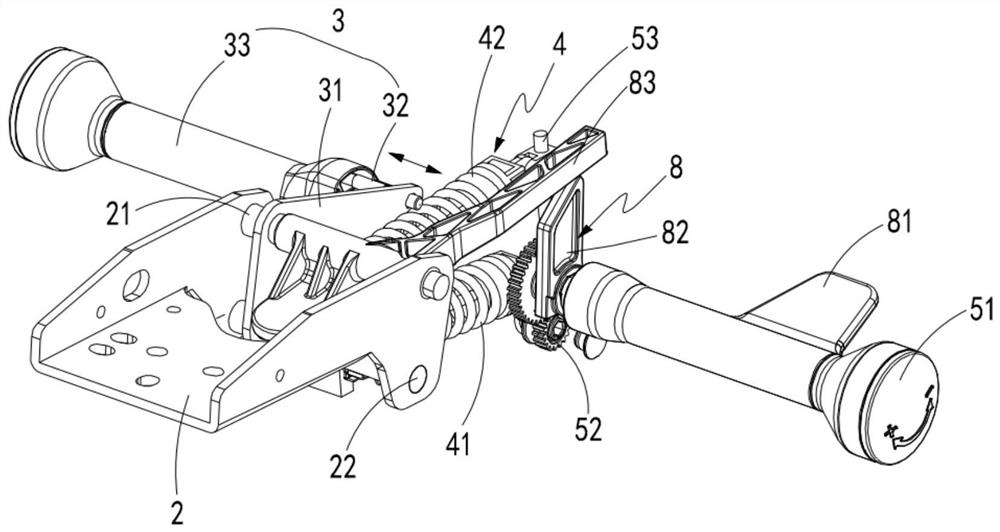
[0069] Such as Figure 4 As shown, in this embodiment, a moving part B55 is also included, and the moving part B55 is sheathed on the screw 53, and the forward and reverse rotation of the screw 53 drives the moving part B55 to reciprocate up and down, and the moving part B55 The member B55 is hinged to drive the second spring 42 to change the included angle of the second spring 42 relative to the first spring 41 .
[0070] Further, one end of the screw 53 is set as a right-handed thread, and the other end is set as a left-handed thread.
[0071] Specifically, the moving part B55 cooperates with the moving part A54 to quickly adjust the included angle of the second spring 42 relative to the first spring 41, so that the backrest mounting plate 2 receives a greater elastic force and the adjustment is faster.
Embodiment 3
[0073] For simplicity, only the difference between embodiment 3 and embodiment 1 or embodiment 2 is described below; the difference between embodiment 3 and embodiment 1 or embodiment 2 is:
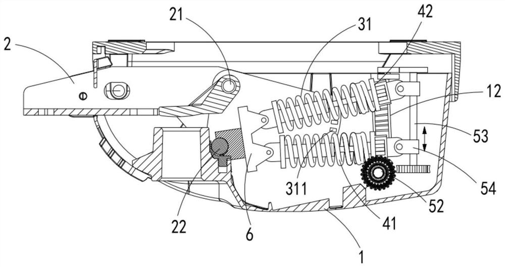
[0074] Such as Figure 5 , 6 As shown, in this embodiment, a number of turns adjustment unit 1 56 is also included, and the number of turns adjustment unit 1 56 is arranged at the end of the first spring 41 to adjust the elastic force of the first spring 41 , so The number of turns adjustment unit one 56 includes a connecting piece 561, a rotating drive wheel a562, a rotating rod 563 and a partition 564, the connecting member 561 connects the first spring 41 and the moving member A54, and the rotating rod 563 rotates Set in the connecting piece 561, the inner wall of the housing 1 is provided with a rack 12, the rotating drive wheel a562 is engaged with the rack 12 for transmission, and the rotating drive wheel a562 drives the rotating rod 563 to rotate, so The spacer 564 is disposed at...
PUM
 Abstract
Description
Claims
Application Information