
Covered stent

A covered stent and film-covered technology, applied in stents, medical science, blood vessels, etc., can solve problems such as aneurysm expansion, rupture, reflux, etc., achieve good flexibility and meet clinical needs

Active Publication Date: 2021-04-06
LIFETECH SCIENTIFIC (SHENZHEN) CO LTD
View PDF12 Cites 0 Cited by
  • Summary
  • Abstract
  • Description
  • Claims
  • Application Information

AI Technical Summary

Problems solved by technology

[0005] The purpose of the present invention is to at least solve the problem that the iliac artery stent is not tightly attached to the wall of the iliac artery after implantation, thereby causing the internal iliac artery blood to flow back into the abdominal aortic aneurysm, causing the aneurysm to continue to expand and even rupture.

Method used


Image

  • Covered stent
  • Covered stent
  • Covered stent

Examples


Embodiment approach 2

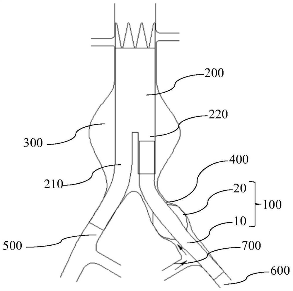
[0074] Such as Figure 11 As shown, the expansion 400 of the common iliac artery in this embodiment is unilateral expansion, and there is no obvious expansion on the opposite side, so the stent graft 100 proposed in this embodiment has an eccentric structure, that is, the cross section of the outer stent 20 is not axisymmetric. , but one side expands significantly more than the other. Except for this difference, the structure of the stent-graft 100 in this embodiment is substantially the same or similar to the structure of the stent-graft 100 in Embodiment 1, and the same or similar parts will not be repeated here.

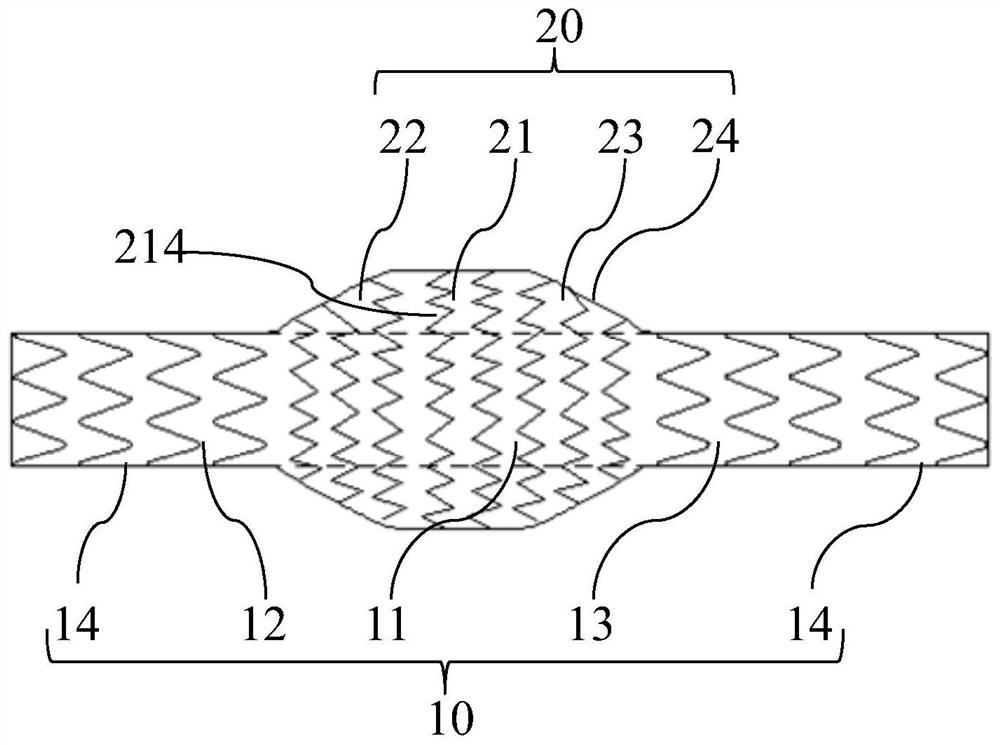
[0075] Specifically, combined with Figure 12 and Figure 13As shown, the stent graft 100 of this embodiment includes an inner stent 10 and an outer stent 20, the inner stent 10 includes a first radial segment 11 and a second radial segment disposed at both ends of the first radial segment 11 12 and the third radial segment 13, the first radial segment 11 has n...

Embodiment approach 3

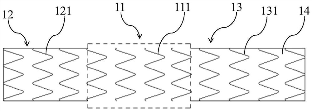
[0078] combine figure 2 and Figure 14 As shown, the structure of the stent graft 100 in this embodiment is substantially the same or similar to the structure of the stent graft 100 in Embodiment 1, and the same or similar parts will not be repeated here. Specifically, the stent graft 100 of this embodiment also includes an inner stent 10 and an outer stent 20. The inner stent 10 includes a first radial segment 11 and a second radial segment disposed at both ends of the first radial segment 11. segment 12 and the third radial segment 13, there is no coating structure on the first radial segment 11, a first coating 14 is provided on the second radial segment 12 and the third radial segment 13, and 20 sets of outer stents Located outside the first radial section 11, the outer stent 20 is provided with a second coating 24, and the outer stent 20 includes a fourth radial section 21 and a fifth radial section arranged at both ends of the fourth radial section 21. To the segment ...

Embodiment approach 4

[0082] combine figure 2 and Figure 17 As shown, the structure of the stent-graft 100 in this embodiment is the same or similar to that of the stent-graft 100 in any one of the first to third embodiments, and the same or similar parts will not be repeated here. The stent graft 100 of this embodiment also includes an inner stent 10 and an outer stent 20 . The difference is that the inner stent 10 includes a first radial segment 11, a second radial segment 12, a third radial segment 13, a seventh radial segment 15 and an eighth radial segment 16, wherein the second radial segment 12 and the third radial section 13 are respectively arranged at both ends of the inner layer stent 10, the seventh radial section 15 is arranged between the first radial section 11 and the second radial section 12, and the eighth radial section 16 is arranged between the first radial segment 11 and the third radial segment 13 . There is no coating structure on the first radial segment 11, the first ...


PUM


Abstract

The invention belongs to the technical field of interventional medical instruments, and particularly relates to a covered stent. The covered stent comprises an inner-layer stent and an outer-layer stent, the inner-layer stent comprises a first radial section, a second radial section and a third radial section, the second radial section and the third radial section are arranged at the two ends of the first radial section respectively, no covering film is arranged on the first radial section, first covering films are arranged on the second radial section and the third radial section respectively, and the first radial section is sleeved with the outer-layer stent. The outer-layer stent comprises a fourth radial section, a fifth radial section and a sixth radial section, the fifth radial section and the sixth radial section are arranged at the two ends of the fourth radial section respectively, second covering films are arranged on the fourth radial section, the fifth radial section and the sixth radial section respectively, and the ends, away from the fourth radial section, of the fifth radial section and the sixth radial section are connected with the inner-layer stent in a sealed mode respectively. According to the covered stent, iliac arteries are completely blocked, blood of the iliac arteries is prevented from flowing back into abdominal aortic aneurysm, the radial size of the covered stent after being compressed is reduced, and therefore the covered stent can adapt to sheathing canals with smaller sizes.

Description

technical field [0001] The invention belongs to the technical field of interventional medical devices, and in particular relates to a covered stent. Background technique [0002] Abdominal aortic aneurysm combined with common iliac artery dilatation is one of the common diseases. With the acceleration of tumor growth, the risk of tumor rupture increases exponentially. Once ruptured, the mortality rate is as high as 90%. Among the 180 million elderly people in my country, there are at least 3 to 4 million patients with abdominal aortic aneurysm. At present, drugs cannot cure it, and its treatment mainly includes traditional open surgery and endovascular repair. The traditional open surgery approach is to perform aneurysm resection followed by artificial vascular reconstruction. However, due to the deep anatomical part of the iliac artery, it is difficult to separate during the operation, the trauma is large, and there are many complications. It has been replaced by endovas...

Claims


Application Information

Patent Timeline
Patent Type & Authority Applications(China)
IPC IPC(8): A61F2/07A61F2/915A61F2/852A61F2/966A61F2/97
CPCA61F2/07A61F2/915A61F2/852A61F2/966A61F2/97A61F2210/0061A61F2210/0066
Inventor 何里明肖本好
Owner LIFETECH SCIENTIFIC (SHENZHEN) CO LTD
Learn More