
Systems and methods with stent and filling structure

a filling structure and system technology, applied in the field of systems and methods with filling structures, can solve the problems of aortic aneurysms, less common and often the most difficult to treat, and patients who are exposed to serious risks

Active Publication Date: 2021-05-25
ENDOLOGIX LLC
View PDF26 Cites 0 Cited by
  • Summary
  • Abstract
  • Description
  • Claims
  • Application Information

AI Technical Summary

Benefits of technology

The patent describes a method for treating an aneurysm using a device that is deployed through a femoral access point on the patient's side. The device includes a first scaffold that has a self-expanding stent or a balloon-expandable stent. The first scaffold is tracked up to the aneurysmal segment and then unsheathed, where the stent is expanded to treat the aneurysm. The technical effect of this method is a minimally invasive and effective treatment for patients with an aneurysm.

Problems solved by technology

Aneurysms are enlargements or bulges in blood vessels that are often prone to rupture and which therefore present a serious risk to a patient.
Thoracic aortic aneurysms are the least common and often the most difficult to treat.
Such open surgical procedures are problematic, however, since access to the abdominal and thoracic aortas is difficult to obtain and because the aorta must be clamped off, placing significant strain on the patient's heart.

Method used


Image

  • Systems and methods with stent and filling structure
  • Systems and methods with stent and filling structure
  • Systems and methods with stent and filling structure

Examples


Embodiment Construction

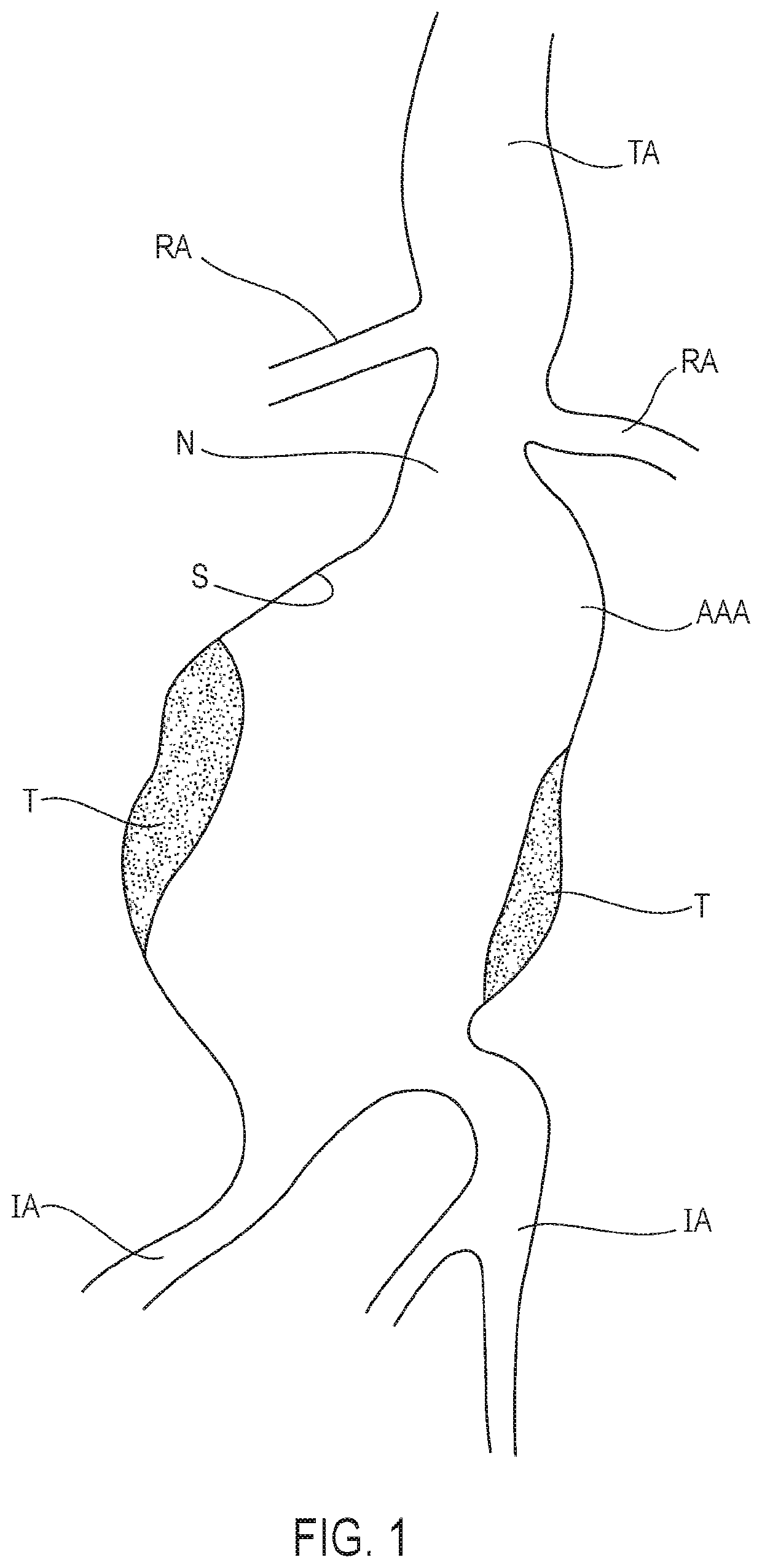
[0050]Referring now to FIG. 1, the anatomy of an infrarenal abdominal aortic aneurysm is illustrated. The thoracic aorta (TA) has renal arteries (RA) at its distal end above the common iliac arteries (IA). The abdominal aortic aneurysm (AAA) typically forms between the renal arteries (RA) and the common iliac arteries (IA) and may have regions of mural thrombus (T) over portions of its inner surface (S). The space between the renal arteries and an upper end of the abdominal aortic aneurysm is typically referred to as a neck area (N) of the aneurysm.

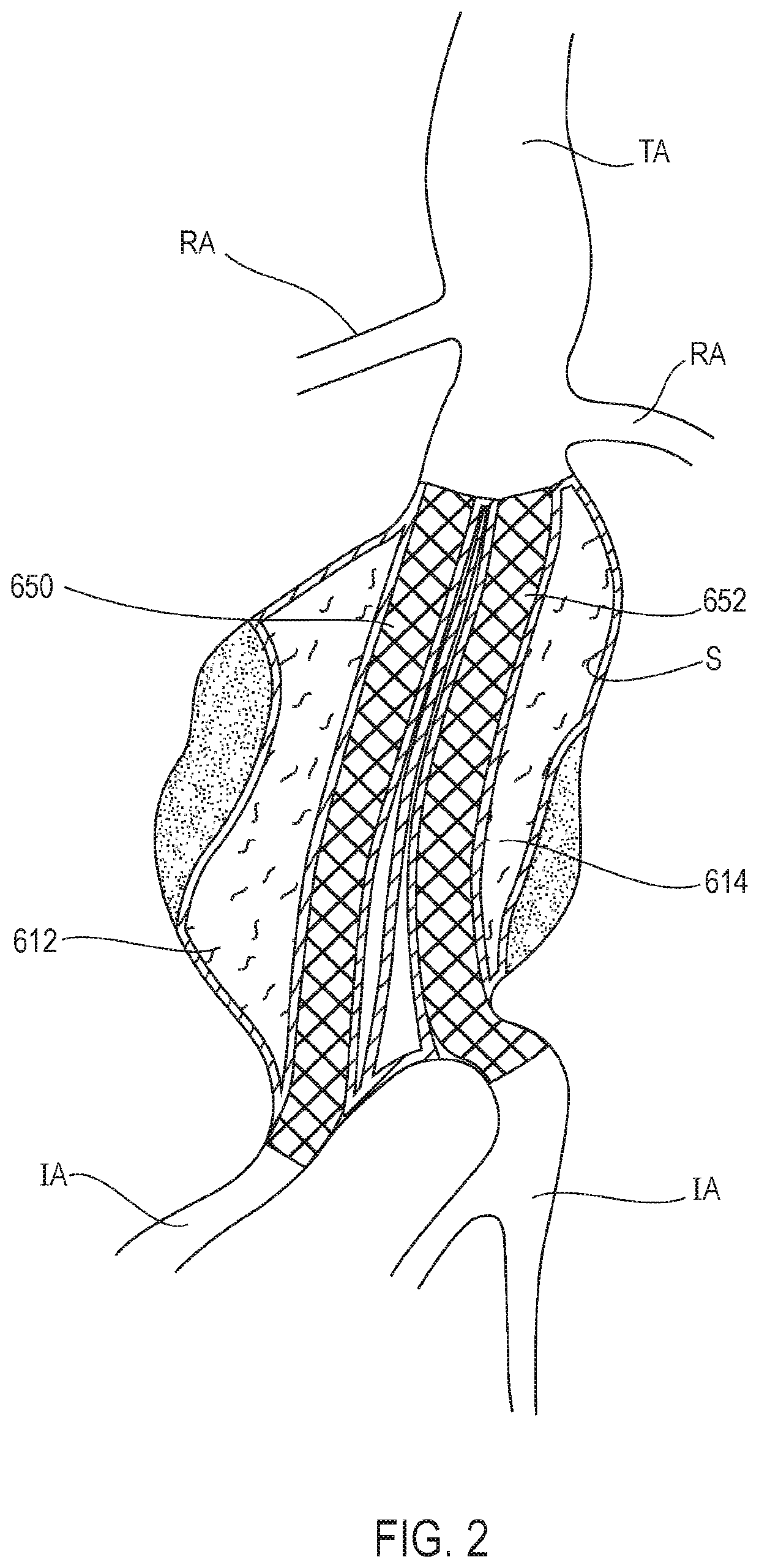
[0051]A type of graft system having filling structures supported by scaffolds for use in an aneurysm is illustrated in FIG. 2, which is a figure from U.S. Pat. No. 8,870,941, titled “Graft Systems Having Filling Structures Supported By Scaffolds And Methods For Their Use,” issued Oct. 28, 2014, the entire contents of which are incorporated by reference herein. With reference to FIG. 2, a first filling structure 612 and a second filling st...


PUM


Abstract

A system includes a filling structure deployable at least partially in a common iliac artery and an external iliac artery, and a scaffold positioned within a first lumen of the filling structure. The scaffold has a fenestration in a side of the scaffold that is positionable toward an internal iliac artery. The filling structure has a second lumen extending from the first lumen and positionable toward the internal iliac artery. A method includes deploying a filling structure at least partially in a common iliac artery and an external iliac artery and positioning a scaffold within a lumen of the filling structure such that a fenestration in a side of the scaffold is positioned toward an internal iliac artery.

Description

CROSS-REFERENCE TO RELATED PATENT APPLICATION[0001]This application claims priority from U.S. Provisional Patent Application No. 62 / 382,207, filed Aug. 31, 2016, the entire contents of which are incorporated by reference herein.FIELD[0002]Embodiments disclosed herein relate generally to systems with filling structures for use in blood vessels and to methods of using systems with filling structures in blood vessels. Various embodiments relate to expandable prosthesis and methods for treating aneurysms.BACKGROUND[0003]Aneurysms are enlargements or bulges in blood vessels that are often prone to rupture and which therefore present a serious risk to a patient. Aneurysms may occur in any blood vessel but are of particular concern when they occur in the cerebral vasculature or the patient's aorta.[0004]Abdominal aortic aneurysms (AAA's) are classified based on their location within the aorta as well as their shape and complexity. Aneurysms that are found below the renal arteries are refer...

Claims


Application Information

Patent Timeline
Patent Type & Authority Patents(United States)
IPC IPC(8): A61F2/07A61F2/06
CPCA61F2/07A61F2002/065A61F2002/072A61F2002/077A61F2210/0085A61F2002/067A61F2002/075
Inventor ORTEGA, CARLOSGOFF, RYANSTONE, ARICNODA, ERIC
Owner ENDOLOGIX LLC
Learn More