Metal plate and processing technology thereof

A processing technology and metal plate technology, applied in printing plate preparation, rotary printing machine, printing, etc., can solve the problems of large mesh limitations, low metal plate precision, single graphics, etc., to achieve full and clear patterns and metal plate precision High, sufficient ink volume effect

Active Publication Date: 2021-04-06
ZHEJIANG SHUOKE SCI & TECH
View PDF20 Cites 0 Cited by
  • Summary
  • Abstract
  • Description
  • Claims
  • Application Information

AI Technical Summary

Problems solved by technology

The problem with the first solution is that the thickness of the connection pattern is the same as that of the functional pattern, and the part of the connection pattern has a relatively large impact on printing, which will reduce the quality of the printed pattern.
The problem with the second scheme is that the thickness of the mesh and the space for wire diameter selection are relatively large, and the compiled graphics are also relatively single.
The metal plates in the above three patents all adopt a two-layer structure, and the two-layer structure needs to be completed by two different processes; Guarantee, resulting in lower accuracy of the obtained metal plate

Method used


Image

  • Metal plate and processing technology thereof
  • Metal plate and processing technology thereof
  • Metal plate and processing technology thereof

Examples


Embodiment 1

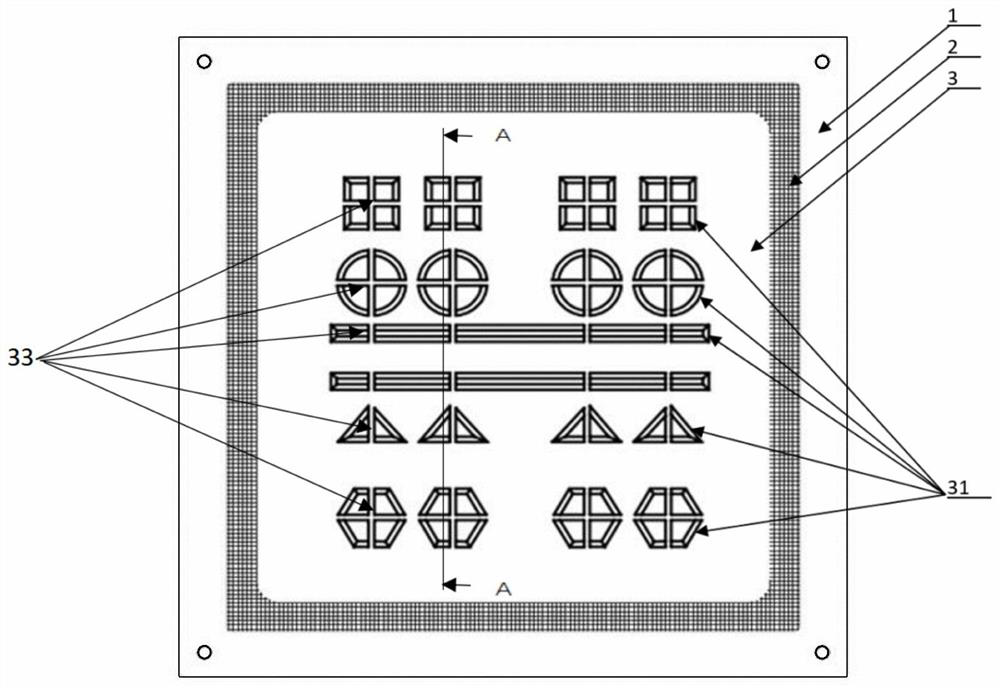
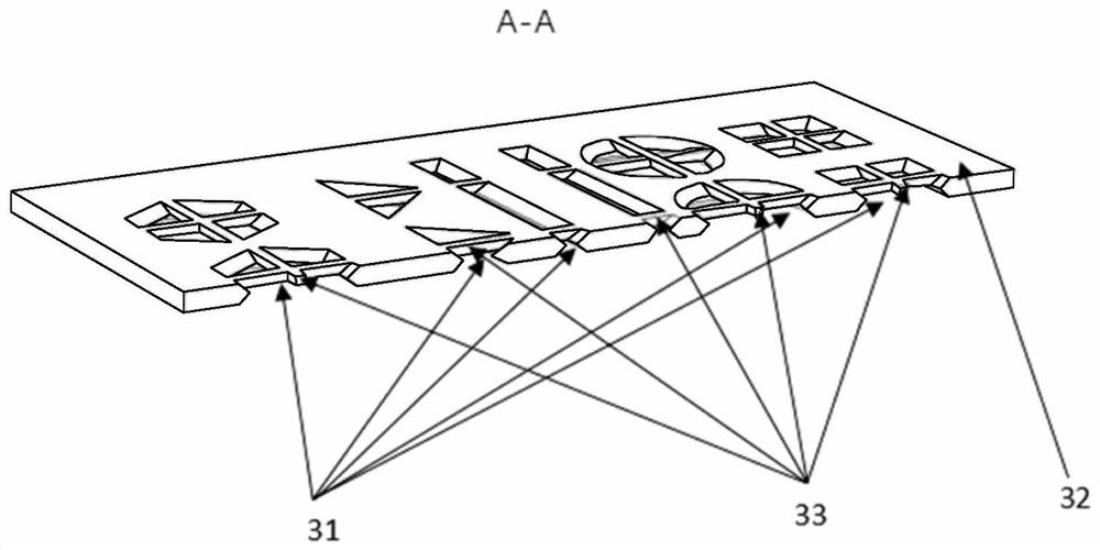
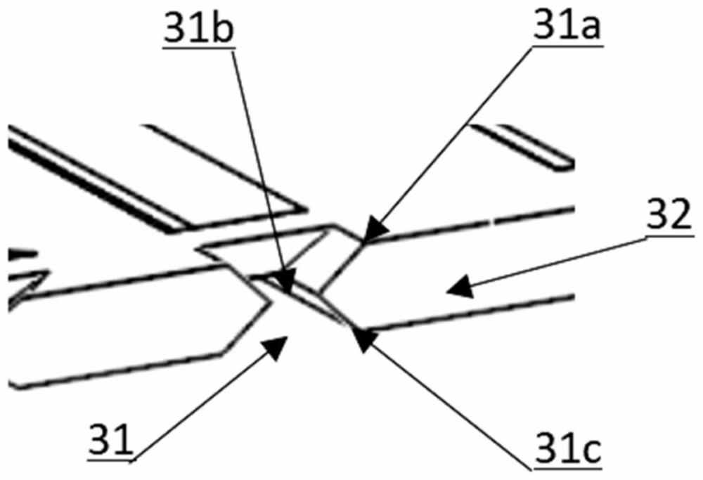
[0055] combine Figure 1-4, a metal plate, including a metal sheet 3, a screen 2 and a screen frame 1, the metal sheet 3 is connected and fixed on the screen frame 1 through the screen 2, and a printing channel 31 is arranged on the metal sheet. The printing channel 31 is surrounded by the non-pattern area on the metal sheet. Connecting units 33 are arranged at intervals along the extending direction of the printing channel 31; the printing channel 31 includes an upper opening 31a, a middle opening 31b, and a lower opening 31c sequentially connected from top to bottom, and the width of the middle opening 31b is the same as the printing design. The width dimensions of the patterns match, and the upper opening 31a and the lower opening 31c are wide-mouthed. Further preferably, 0

[0056] In this embodiment, preferably, the width of the upper...

Embodiment 2

[0059] This embodiment also discloses a raw metal plate processing technology, including the following steps

[0060] S1: Pretreat the surface of the metal sheet 32 ​​by selecting a metal sheet 32 ​​with a thickness ranging from 0.005 to 0.2 mm; preferably, the step of surface pretreatment of the metal sheet 32 ​​includes removing grease and other dirt on the surface of the metal sheet.

[0061] S2: a layer of etching photosensitive material is attached to both sides of the metal sheet 32;

[0062] S3: Exposure: Expose the design patterns on both sides of the metal sheet 32;

[0063] S4: Developing: performing a developing operation on both sides of the exposed metal sheet 32;

[0064] S5: Etch both sides of the developed metal sheet 32; specifically, in this embodiment, in the process of etching the upper opening 31a, the middle opening 31b, and the lower opening 31c of the printing channel 31, the etching time and the etching time can be adjusted. The temperature, pressure...

Embodiment 3

[0069] This embodiment also discloses a metal screen processing technology, including the following steps

[0070] S1: select metal sheets within the thickness range of 0.005-0.2 mm, and perform surface pretreatment; including cleaning the surface of the metal sheet 32, removing grease and other dirt on the surface of the metal sheet 32.

[0071] S2: Carry out laser engraving patterns on one surface of the metal sheet 32, and the depth of the pattern on this surface and the width of the cross-sections of regions with different depths are controlled and obtained by adjusting the laser power and the number of engraving times.

[0072] S3: Turn over the metal sheet 32, and perform corresponding laser pattern engraving on the other surface of the metal sheet 32, and perform corresponding pattern engraving on the other surface of the metal sheet 32 ​​after the laser is precisely aligned. In this embodiment, during the process of engraving the upper opening 31 a , the middle opening...


PUM

PropertyMeasurementUnit
thicknessaaaaaaaaaa
thicknessaaaaaaaaaa

Abstract

The invention discloses a metal plate. The metal plate comprises a metal sheet, a silk screen and a screen frame, wherein the metal sheet is fixedly connected to the screen frame through the silk screen, a printing channel is arranged on the metal sheet, the printing channel is defined by a non-pattern area on the metal sheet, and connecting units are arranged at intervals in the extending direction of the printing channel; the printing channel comprises an upper opening, a middle opening and a lower opening which are sequentially connected from top to bottom, the size of the middle opening is matched with the size of a printing design pattern, and the upper opening and the lower opening are in a wide opening shape. In addition, the invention further discloses a processing technology of three metal plates. Compared with the metal plate with two layer structures obtained by forming twice in the prior art, the metal plate is of an integral structure which is integrally formed, such that the technology is simplified greatly and the metal plate is higher in precision.

Description

technical field [0001] The invention belongs to the field of printing screens, in particular to a metal screen. Background technique [0002] Traditional metal screens often adopt two schemes. The first scheme is to process only one metal layer by electroplating. This metal layer contains all the patterns, including functional patterns and connection patterns. The problem with the first solution is that the thickness of the connection pattern is the same as that of the functional pattern, and the part of the connection pattern has a relatively large impact on printing, which will reduce the quality of the printed pattern. [0003] The second solution is a metal film version, and the functional pattern layer is made on the mesh. This similar product is to combine the functional pattern layer with the mesh through electroplating, gluing, welding, deposition and other methods. The problem of the second kind of scheme is that the thickness of the gauze and the limitation of th...

Claims


Application Information

Patent Timeline
Patent Type & Authority Applications(China)
IPC IPC(8): B41F15/36B41C1/14C25D1/00
CPCB41F15/36B41C1/14B41C1/148C25D1/00Y02E60/10
Inventor 章征国蒋豪跃
Owner ZHEJIANG SHUOKE SCI & TECH
Why Eureka
Try Eureka