Exhaust pipe decorative cover

A technology for decorative covers and exhaust pipes, which is applied in the direction of exhaust devices, noise reduction devices, engine components, etc., and can solve problems such as long flanges of electroplated frames, insufficient strength, increased area of ​​electroplated parts, and related product costs.

Active Publication Date: 2021-04-06
CHERY AUTOMOBILE CO LTD
View PDF7 Cites 0 Cited by
  • Summary
  • Abstract
  • Description
  • Claims
  • Application Information

AI Technical Summary

Problems solved by technology

[0003] In the prior art, the exhaust pipe decoration cover mostly adopts the shape feature that the outer frame is a U-shaped electroplated frame, and the inner plate is a black leather-patterned part. Modeling structure, if the inner plate adopts the traditional U-shaped groove + cantilever clamping structure, in order to avoid the thickness of the mold at this place being too thin and resulting in insufficient strength, plus the double-layer material thickness of the U-shaped groove, the width of the U-shaped groove should not be too small ;In addition, in order to ensure the elasticity of the clamping structure, the length of the cantilever should not be short, which will cause the clamping surface of the outer frame and the inner plate to be relatively backward, resulting in longer flanges of the electroplated outer frame, thereby increasing the area of ​​the electroplated parts and Related product cost

Method used


Image

  • Exhaust pipe decorative cover
  • Exhaust pipe decorative cover
  • Exhaust pipe decorative cover

Examples


Embodiment Construction

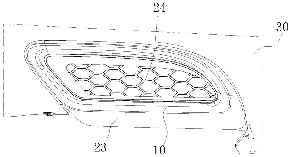
[0016] For the convenience of explanation, the following problems are first defined: the direction of vehicle length is X direction, the direction of vehicle width is direction Y, and the direction of vehicle height is Z direction. The exhaust pipe decoration cover is installed at the rear of the car for the purpose of left-right symmetry and beauty. A fake trim cover where the exhaust pipes would be.

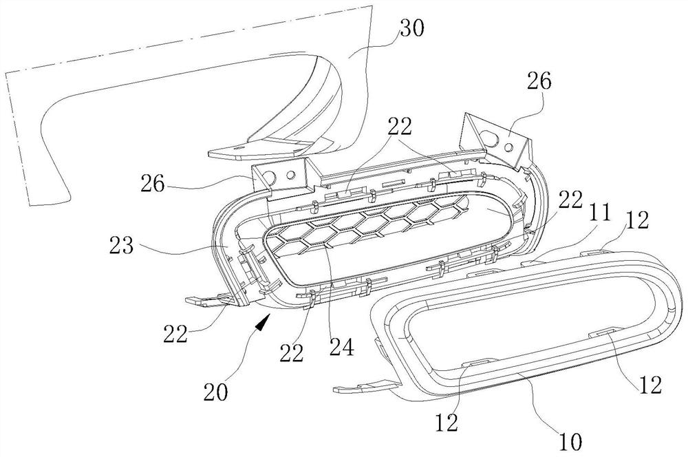
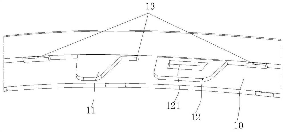
[0017] An exhaust pipe decorative cover, comprising an outer frame 10 and an inner panel 20, a Y-direction positioning tongue 11 and a snap-in piece 12 protrude from the edge of the outer frame 10 toward the inner panel 20, and the Y-direction positioning tongue 11 It is inserted into the positioning hole 21 provided on the inner plate 20 to form a Y-direction positioning fit. The snap-in piece 12 is provided with a square hole 121, and the inner plate 20 is provided with a snap-in body 22 at a position corresponding to the snap-in piece 12. The connecting body 22 is engaged wi...


PUM


Abstract

The invention provides an exhaust pipe decorative cover. According to the exhaust pipe decorative cover, on the premise that the matching reliability of an electroplating outer frame and an inner plate is guaranteed, the flanging of the electroplating outer frame is small in length, light in weight and low in cost. The exhaust pipe decorative cover is characterized in that a Y-direction positioning tongue piece and a clamping piece are arranged on the frame edge of the outer frame in the mode of protruding towards the inner plate, and the Y-direction positioning tongue piece is inserted into a positioning hole formed in the inner plate to form Y-direction positioning matching; and a square hole is formed in the clamping piece, a clamping body is arranged at the position, corresponding to the clamping piece, of the inner plate, the clamping body is matched with the square hole in a clamped mode, and a hollowed-out deformation hole is formed in the position, close to the clamping body, of the inner plate. Compared with a common double-layer U-shaped groove structure, a single-layer clamping body structure is adopted, the requirement for the longitudinal space is small, in addition, in order to keep the elasticity of the clamping body, the bottom of the clamping body is hollowed out, the elasticity of the clamping body is not kept by increasing the length of a cantilever commonly, the clamping position of the inner plate and the outer frame is effectively shortened, therefore, the flanging length of the outer frame is shortened, and the purposes of weight reduction and cost reduction are achieved.

Description

technical field [0001] The invention relates to the technical field of automobile exhaust pipes, in particular to an exhaust pipe decorative cover. Background technique [0002] Automobile exhaust pipes are generally divided into two types: exposed and hidden. Among them, the exposed exhaust pipes are generally covered with decorative covers to increase the sense of refinement and sportiness of the vehicle. With the continuous improvement of the exterior shape and refined design of automobiles, more and more models choose to design exposed exhaust pipe decorative covers to highlight the overall sporty feeling of the vehicle, but it is limited by the space layout of the exhaust system and The platform of the exhaust pipe continues to meet the requirements, and some models choose to use the exhaust pipe decorative cover, that is, the exhaust pipe decorative cover is not directly facing the car exhaust pipe, but the interior of the decorative cover is a sealing structure, and t...

Claims


Application Information

Patent Timeline
IPC IPC(8): F01N13/08F01N13/18
CPCF01N13/08F01N13/18
Inventor 徐劲风孔令春吴鹏李伟卢宗银陈强王存峰
Owner CHERY AUTOMOBILE CO LTD
Why Eureka
Try Eureka