Dehydration equipment

A technology for dehydration equipment and water outlet holes, which is applied in lighting and heating equipment, drying solid materials, dryers, etc., and can solve the problems of blocked outlets and pressure plates that cannot effectively achieve dehydration

Inactive Publication Date: 2021-04-06
SUZHOU JONO RECYCLING RESOURCES EQUIP
View PDF10 Cites 2 Cited by
  • Summary
  • Abstract
  • Description
  • Claims
  • Application Information

AI Technical Summary

Problems solved by technology

[0004] However, the existing dehydration equipment has the risk of blocking the outlet when the particle size of the material is too large, and the pressure plate cannot effectively dehydrate the material if the particle size is too small

Method used


Image

  • Dehydration equipment
  • Dehydration equipment
  • Dehydration equipment

Examples


Embodiment Construction

[0028] The present invention will be described in detail below in conjunction with specific embodiments shown in the accompanying drawings. However, these embodiments do not limit the present invention, and any structural, method, or functional changes made by those skilled in the art according to these embodiments are included in the protection scope of the present invention.

[0029] In each drawing of the present invention, for convenience of illustration, some dimensions of structures or parts are exaggerated relative to other structures or parts, and therefore, are only used to illustrate the basic structure of the subject matter of the present invention.

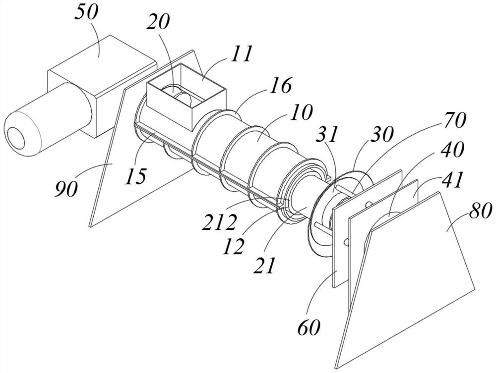
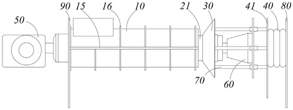
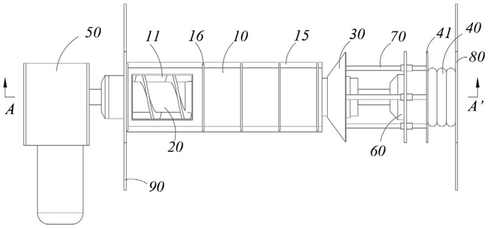
[0030] Such as figure 1 , figure 2 , image 3 and Figure 4 As shown, one embodiment of the present invention provides a kind of dehydration equipment, comprising:

[0031] A sieve cylinder 10 is provided with an inlet 11 and an outlet 12 on the sieve cylinder 10 . Materials can enter the inside of the screen dru...


PUM


Abstract

The invention discloses dehydration equipment, which comprises a screen drum, and a feeding port and a discharging port are arranged on the screen drum; a material conveying mechanism comprising a conveying part arranged between the feeding port and the discharging port; an extension piece, wherein gap is formed between the extrusion part and the discharging port; a driving piece connected with one end, far away from the discharging port, of the extrusion piece; and the driving piece drives the extrusion piece to move away from or close to the discharging port. Materials are moved from the feeding port to the discharging port through the material conveying mechanism, the extension piece extrudes the materials at the discharging port to dehydrate the materials, the driving piece drives the extension piece to move, so that the distance between the extension piece and the discharging port is changed, the materials with large particle sizes and the materials with small particle sizes can be dehydrated, and the discharging port cannot be blocked.

Description

technical field [0001] The invention relates to the field of dehydration, in particular to a dehydration device. Background technique [0002] Dehydration equipment is equipment used for coagulation and dehydration. Before fermentation, organic waste needs to be dehydrated by dehydration equipment. After dehydration, the humidity of organic waste decreases, which can shorten the subsequent fermentation cycle of organic waste. [0003] An existing dehydration device includes a cylinder shell, a main shaft, and a pressure plate. One end of the cylinder shell is provided with a feed port, and the other end is provided with a discharge port. The main shaft is arranged along the axial direction of the cylinder shell and at least a part is located between the feed inlet and the discharge outlet, and a helical blade is arranged on the main shaft. When the main shaft rotates, the spiral blade drives the material to move from the feed port to the discharge port, and the pressure pl...

Claims


Application Information

Patent Timeline
Patent Type & Authority Applications(China)
IPC IPC(8): F26B5/14F26B17/20F26B25/00F26B25/02F26B25/12F26B25/16
CPCF26B5/14F26B17/20F26B25/002F26B25/16F26B25/12F26B25/02
Inventor 袁靖周翔张鑫
Owner SUZHOU JONO RECYCLING RESOURCES EQUIP
Why Eureka
Try Eureka