Dimensional positioning pose simulation matching method based on two three-coordinate positioners

A three-coordinate locator and matching method technology, which is applied in design optimization/simulation, special data processing applications, geometric CAD, etc., can solve problems such as error-prone, complex configuration environment steps, and unfavorable promotion of simulation applications

Active Publication Date: 2021-04-06
CHENGDU AIRCRAFT INDUSTRY GROUP
View PDF14 Cites 4 Cited by
  • Summary
  • Abstract
  • Description
  • Claims
  • Application Information

AI Technical Summary

Problems solved by technology

However, the attitudes of each aircraft are inconsistent, resulting in changes in the position of the actual locator. In order to ensure the safety of the CNC machining program running in the subsequent automatic hole-making process, it is necessary to establish a simulation that is consistent with the actual hole-making machine tool. The environment is exactly the same as the simulation environment to ensure the authenticity of the simulation environment. Therefore, each product must configure the simulation environment according to the actual location of the locator and the dimension frame. Due to the complicated steps of configuring the environment, and there are many components that need to be configured. , therefore, error-prone during the configuration process and is not conducive to the promotion of simulation applications
At the same time, in the actual environment, the driven end of the dimensional positioning tool can follow the movement of the active end, but in the simulation software, the driven end of the dimensional positioning tool cannot follow the active end. The simulation of type positioning tooling brings problems that do not match the actual environment

Method used


Image

  • Dimensional positioning pose simulation matching method based on two three-coordinate positioners
  • Dimensional positioning pose simulation matching method based on two three-coordinate positioners
  • Dimensional positioning pose simulation matching method based on two three-coordinate positioners

Examples


Embodiment 1

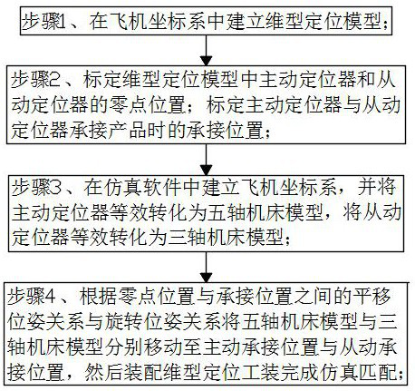
[0042] A kind of three-dimensional positioning pose simulation matching method based on two three-coordinate locators in this embodiment, such as figure 1 shown, including the following steps:

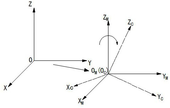
[0043] Step 1. Establish the aircraft coordinate system O-XYZ, and establish a dimensional positioning model in the aircraft coordinate system, such as Figure 7 As shown, and establish the active positioner 01 and the driven positioner 02 in the dimensional positioning model, and then establish the dimensional positioning tool 03 between the active positioner 01 and the driven positioner 02;

[0044] In the actual environment, the active positioner 01 and the driven positioner 02 are controlled by the control system, so that both the active positioner 01 and the driven positioner 02 move to the zero point, and then the laser tracker is used to calibrate the active positioner 01 and the driven positioner at this time. The zero position of locator 02 in the aircraft coordinate system. ...

Embodiment 2

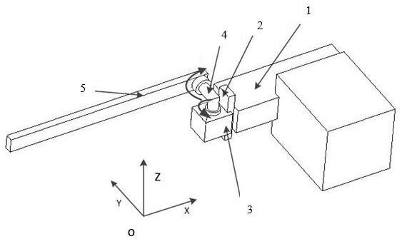
[0065] This embodiment is further optimized on the basis of Embodiment 1, and the active locator 01 is equivalently transformed into figure 2 The steps for the five-axis machine tool model shown include:

[0066] Step A1, establish the aircraft coordinate system O-XYZ in the simulation software, and set the active machine tool according to the zero position calibrated in step 1, move and set the X-axis component 1 on the active machine tool along the X-axis direction, and move the X-axis component 1 along the X-axis component 1 The Y-axis component 2 is set by moving in the Y-axis direction, and the Z-axis component 3 is set by moving along the Z-axis direction on the Y-axis component 2;

[0067] The X-axis component 1 can move along the X-axis direction to realize the translation of the simulated active positioner 01 along the X-axis direction; the Y-axis component 2 can move along the Y-axis direction to realize the simulated translation of the active positioner 01 along th...

Embodiment 3

[0073] This embodiment is further optimized on the basis of the above-mentioned embodiment 1 or 2. The step of equivalently transforming the driven positioner 02 into a three-axis machine tool model is to establish the aircraft coordinate system O-XYZ in the simulation software, and according to step 1 Set the slave machine tool at the zero position calibrated in , set the X-axis component 1 on the slave machine tool along the X-axis direction, set the Y-axis component 2 on the X-axis component 1 along the Y-axis direction, and set the Y-axis component 2 on the Y-axis component 2 along the Z axis. Axis movement sets Z-axis component 3.

[0074] The X-axis component 1 can move along the X-axis direction to realize the translation of the simulated driven positioner 02 along the X-axis direction; the Y-axis component 2 can move along the Y-axis direction to realize the simulated driven positioner 02 along the Y-axis The translation in the direction; the Z-axis component 3 can mov...


PUM


Abstract

The invention discloses a dimensional positioning pose simulation matching method based on two three-coordinate positioners. The method comprises the steps of: calibrating zero point positions, driving bearing positions and driven bearing positions of a driving positioner and a driven positioner, enabling the driving positioner to be equivalent to a five-axis machine tool model, enabling the driven positioner to be equivalent to a three-axis machine tool model, obtaining translation parameters and rotation parameters of the five-axis machine tool model by calculating a translation pose relationship and a rotation pose relationship between the zero point position and the active bearing position; and obtaining translation parameters of the three-axis machine tool model by calculating a translation pose relationship between the zero point position and the driven bearing position. Therefore, the simulation movement of a dimensional positioning tool is converted into translation rotation of the five-axis machine tool model and translation of the three-axis machine tool model, so that the simulation environment of the dimensional positioning tool is consistent with the actual environment, and automatic matching of the dimensional positioning tool and a positioner in the simulation environment is realized.

Description

technical field [0001] The invention belongs to the technical field of aircraft component pose adjustment simulation, and in particular relates to a dimensional positioning pose simulation matching method based on two three-coordinate locators. Background technique [0002] In recent years, the concept of developing digital assembly has become more and more popular. During the digital assembly process of an aircraft, the interconnected parts, assemblies and components must maintain the correct position and attitude, so their support method is very critical. Considering the pose adjustment requirements of aircraft components and components, it is usually supported by a pose adjustment unit composed of at least two three-coordinate numerical control positioners. However, the attitudes of each aircraft are inconsistent, resulting in changes in the position of the actual locator. In order to ensure the safety of the CNC machining program running in the subsequent automatic hole...

Claims


Application Information

Patent Timeline
Patent Type & Authority Applications(China)
IPC IPC(8): G06F30/15G06F30/17G06F30/20
CPCG06F30/15G06F30/17G06F30/20
Inventor 刘均谢颖李杰康志文杨京京谯成李松马振博
Owner CHENGDU AIRCRAFT INDUSTRY GROUP
Why Eureka
Try Eureka