Main shielding case of vacuum arc-extinguishing chamber and vacuum arc-extinguishing chamber

A technology of vacuum interrupter and shielding cover, which is applied in the direction of high-voltage air circuit breakers, electrical components, electric switches, etc., can solve the problems of unfavorable miniaturization and great influence of metal vapor on insulation performance, so as to improve the fixing reliability and benefit Effects of miniaturization and reduction in axial dimension

Pending Publication Date: 2021-04-06
TIANJIN PINGGAO INTELLIGENT ELECTRIC +2
View PDF1 Cites 1 Cited by
  • Summary
  • Abstract
  • Description
  • Claims
  • Application Information

AI Technical Summary

Problems solved by technology

[0005] The purpose of the present invention is to provide a main shielding cover of a vacuum interrupter, which solves the problem that the insulation performance of the vacuum interrupter in the prior art is greatly affected by metal vapor and is not conducive to miniaturization

Method used


Image

  • Main shielding case of vacuum arc-extinguishing chamber and vacuum arc-extinguishing chamber
  • Main shielding case of vacuum arc-extinguishing chamber and vacuum arc-extinguishing chamber
  • Main shielding case of vacuum arc-extinguishing chamber and vacuum arc-extinguishing chamber

Examples


Embodiment 1

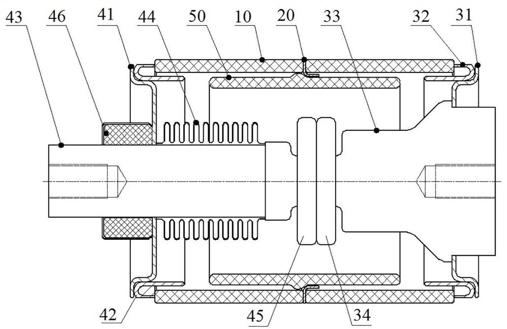
[0052] Such as figure 1 As shown, the vacuum interrupter is a 126kv vacuum interrupter, including a hollow shell 10, the shell 10 is an existing structure, made of ceramic material, the shell 10 is a two-stage structure spliced ​​with each other, the two-stage shell 10 They are fixedly connected by a metal intermediate sealing ring 20. The two axial ends of the casing 10 are respectively provided with a static contact 34 assembly and a moving contact 45 assembly, and the casing 10 is provided with a main shield 50 in the axial middle.

[0053] The static contact 34 assembly includes a static cover 31, a static end shield 32, and also includes a static conductive rod 33 and a static contact 34. The static cover 31, the static end shield 32 and the static conductive rod 33 are welded and fixed together. The contact 34 is fixed on the static conductive rod 33 .

[0054] The moving contact 45 assembly includes a moving cover plate 41, a moving end shield 42, and also includes a ...

Embodiment 2

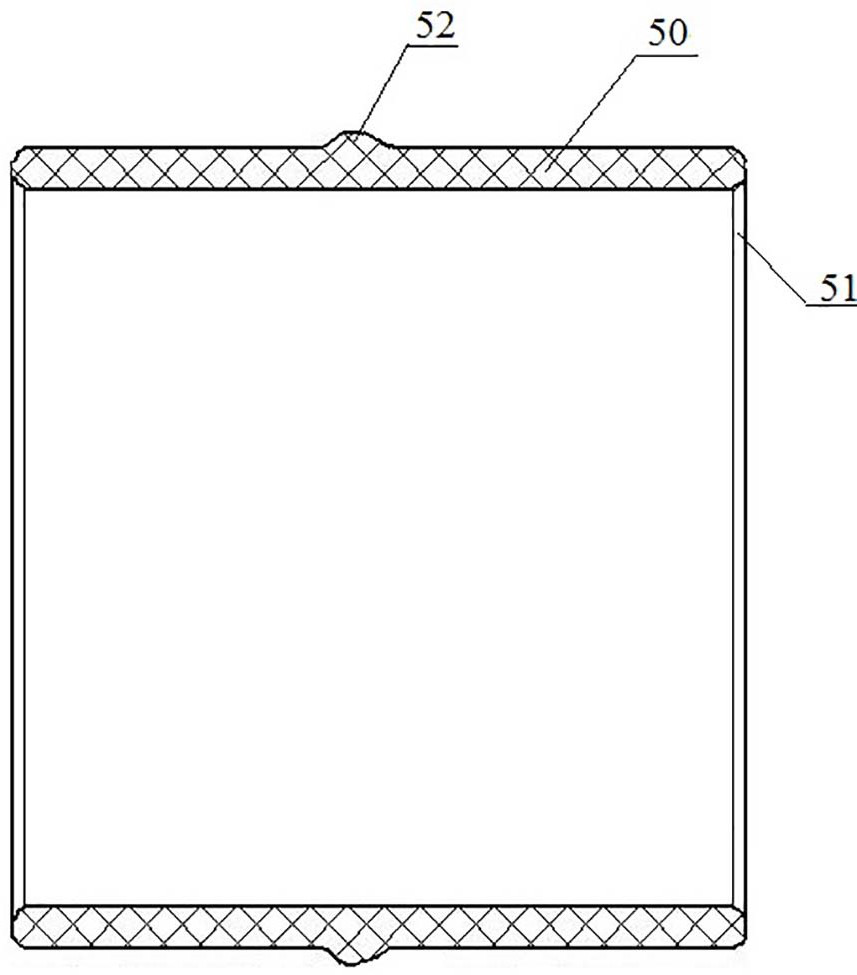
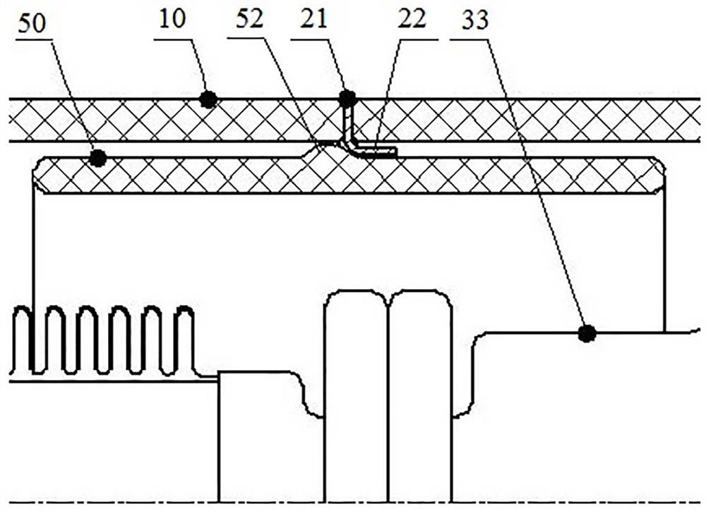
[0061] The difference between this embodiment and Embodiment 1 is that in Embodiment 1, an annular protrusion 52 is provided on the outer peripheral surface of the main shield 50, and a metallized layer is provided on the surface of the annular protrusion 52, while in this embodiment , the outer peripheral surface of the main shielding case 50 is a flat surface, which is directly welded to the metal middle sealing ring 20 .

[0062] Embodiment of the main shielding cover of the vacuum interrupter in the present invention: the embodiment of the main shielding cover of the vacuum interrupter is the main shielding cover 50 recorded in any embodiment of the above-mentioned vacuum interrupter, which is no longer detailed here illustrate.


PUM


Abstract

The invention relates to a main shielding case of a vacuum arc-extinguishing chamber and the vacuum arc-extinguishing chamber. The vacuum arc-extinguishing chamber comprises two sections of shells, a main shielding case and a metal middle sealing ring, wherein the two sections of shells are in butt joint in the axial direction of the vacuum arc-extinguishing chamber; the main shielding case is used for surrounding the outer side of the joint of the moving contact and the static contact; the metal middle sealing ring is welded and fixed between the two sections of shells and is used for welding and fixing the main shielding case; the main shielding case is made of a ceramic material; a metallization layer is arranged on the outer peripheral surface of the main shielding case; and the metallization layer is arranged around the outer peripheral surface of the main shielding case to form a middle sealing ring connecting part which is used for being welded and fixed with a metal middle sealing ring between two sections of shells of the vacuum arc-extinguishing chamber so as to realize the fixation of the main shielding case. According to the scheme, the problem that the insulation performance of the vacuum arc-extinguishing chamber in the prior art is greatly influenced by metal vapor and miniaturization is not facilitated can be solved.

Description

technical field [0001] The invention relates to a main shielding cover of a vacuum interrupter and a vacuum interrupter. Background technique [0002] With the continuous development of the electric power industry and the improvement of social requirements for environmental protection, vacuum interrupters are developing towards high-voltage power transmission and distribution, and switchgear using vacuum interrupters are also developing towards high voltage and miniaturization. The volume of the vacuum interrupter is an important factor for the overall volume of the switchgear. Therefore, the high voltage and miniaturization of the vacuum interrupter are the basis for the miniaturization of the switchgear. However, with the increase of the voltage level, the requirements for the internal insulation performance of vacuum interrupter products are also getting higher and higher. [0003] The existing vacuum interrupter, such as the one disclosed in the Chinese patent document ...

Claims


Application Information

Patent Timeline
Patent Type & Authority Applications(China)
IPC IPC(8): H01H33/662H01H33/664
CPCH01H33/66261H01H33/664H01H2033/66269
Inventor 刘世柏李小钊赵芳帅薛从军李锟刘心悦亓春伟齐大翠王宇浩刘畅姚新伟李仁峰刘晶晶郑乐乐海竣超李相兵苏文豪郭润涛白丽娜孙宇陈高攀霍然姚锋娟齐婵焦淑敏
Owner TIANJIN PINGGAO INTELLIGENT ELECTRIC
Why Eureka
Try Eureka