
High-peak-power single-frequency narrow-linewidth nanosecond triangular short-pulse fiber laser

A technology of fiber lasers and pulsed lasers, which is applied to lasers, laser components, phonon exciters, etc., can solve the problems that lasers cannot achieve the desired effect, and achieve industrialized mass production, small optical path loss, and stable operation. Effect

Active Publication Date: 2021-04-06
TIANJIN UNIV
View PDF4 Cites 1 Cited by
  • Summary
  • Abstract
  • Description
  • Claims
  • Application Information

AI Technical Summary

Problems solved by technology

[0003] The traditional method is to offset the influence of self-phase modulation through phase pre-compensation, but due to the performance of the phase compensation device, this method cannot achieve the desired effect in high peak power lasers

Method used


Image

  • High-peak-power single-frequency narrow-linewidth nanosecond triangular short-pulse fiber laser
  • High-peak-power single-frequency narrow-linewidth nanosecond triangular short-pulse fiber laser
  • High-peak-power single-frequency narrow-linewidth nanosecond triangular short-pulse fiber laser

Examples


Embodiment 1

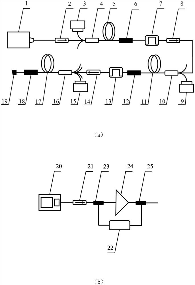
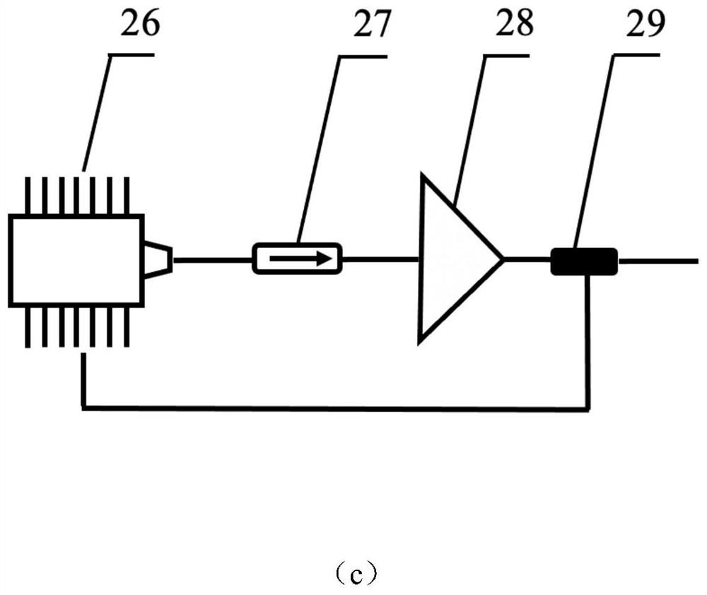
[0050] A high-peak-power single-frequency narrow-linewidth triangular nanosecond short-pulse fiber laser adopts a MOPA structure with two-stage power pre-amplification and one-stage power main amplifier stage. For its implementation, see figure 1 (a), comprising: a pulsed laser seed source 1, a first isolator 2, a first pumping source 3, a first beam combiner 4, a first double-clad active optical fiber 5, and a first cladding optical stripper 6 , the first bandpass filter 7, the second isolator 8, the second pumping source 9, the second beam combiner 10, the second double-clad active fiber 11, the second cladding optical isolator 12, the second Bandpass filter 13, third isolator 14, third pumping source 15, third beam combiner 16, third double-clad active optical fiber 17, third cladding optical stripper 18, collimator outputter 19 .

[0051] Wherein, the first pump source 3, the first beam combiner 4, the first double-clad active optical fiber 5, the first cladding optical s...

Embodiment 2

[0065] A high peak power single-frequency narrow-linewidth triangular nanosecond short-pulse fiber laser, using a MOPA structure with two-stage power pre-amplification and one-stage power main amplification, see figure 1 (a), comprising: a pulsed laser seed source 1, a first isolator 2, a first pumping source 3, a first beam combiner 4, a first double-clad active optical fiber 5, and a first cladding optical stripper 6 , the first bandpass filter 7, the second isolator 8, the second pumping source 9, the second beam combiner 10, the second double-clad active fiber 11, the second cladding optical isolator 12, the second Bandpass filter 13, third isolator 14, third pumping source 15, third beam combiner 16, third double-clad active optical fiber 17, third cladding optical stripper 18, collimator outputter 19 .

[0066] Wherein, the first pump source 3, the first beam combiner 4, the first double-clad active optical fiber 5, the first cladding optical stripper 6, the first bandp...


PUM

PropertyMeasurementUnit
wavelengthaaaaaaaaaa
poweraaaaaaaaaa

Abstract

The invention discloses a triangular pulse-based high-power single-frequency narrow-linewidth nanosecond short-pulse fiber laser. An optical signal output by a pulse laser seed source is injected into a first power pre-amplification stage through a first isolator; the optical signal amplified by the first power pre-amplification stage is then injected into a second power pre-amplification stage to be amplified again and then injected into a main amplification stage; the pulse laser seed source adopts a continuous laser intensity modulation mode or a semiconductor butterfly laser direct modulation mode to obtain a triangular laser pulse with a rapid rising edge. According to the characteristics of narrow triangular pulse intrinsic line width and inhibition effect on self-phase modulation, triangular pulse single-frequency pulse laser is used as a seed source, and peak power is amplified through a main oscillation power amplification structure.

Description

technical field [0001] The invention relates to the field of fiber lasers, in particular to a triangular pulse-based high-peak-power single-frequency narrow-linewidth nanosecond short-pulse fiber laser. Background technique [0002] All-fiber high-power narrow-linewidth single-frequency nanosecond pulsed Ytterbium-doped fiber lasers are widely used in radar, remote sensing and other fields because of their good durability, compact structure and maintenance-free characteristics. And in these fields, laser light sources with narrow linewidth can greatly improve the overall performance of the system, so it is of great significance to study nanosecond pulsed fiber lasers with narrow linewidth. One of the important reasons for limiting nanosecond pulsed fiber lasers is the self-phase modulation effect. In the process of pulse amplification, as the peak power increases, the severe self-phase modulation effect will cause serious broadening of the linewidth. [0003] The traditiona...

Claims


Application Information

Patent Timeline
Patent Type & Authority Applications(China)
IPC IPC(8): H01S3/067H01S3/00H01S3/11
CPCH01S3/06754H01S3/0085H01S3/0057H01S3/0071H01S3/11H01S3/1618H01S3/0078H01S3/0064H01S3/06758H01S3/094007H01S3/1003H01S2301/03H01S2301/08H01S3/06716H01S3/06733H01S3/094065H01S3/094069H01S3/0941H01S3/1068H01S3/107H01S3/2308
Inventor 史伟史朝督田浩盛泉姚建铨
Owner TIANJIN UNIV
Learn More