A cable connection box for power distribution cabinet

A technology for cable connection and power distribution cabinets, which is applied in substation/distribution device casings and electrical components, etc., can solve the problems of rain-proof shelters affecting the operation space, etc., and achieve the effect of simple structure, good rain-proof and convenient rain-proof

Active Publication Date: 2022-07-15
恒凯电力设备有限公司
View PDF11 Cites 0 Cited by
  • Summary
  • Abstract
  • Description
  • Claims
  • Application Information

AI Technical Summary

Problems solved by technology

[0003] The cable connection box needs to open the cover when operating the cable end connection, and the top of the box will be equipped with a rainproof shed, so the operation space will be affected by the existence of the rainproof shed after the cover is opened.

Method used


Image

  • A cable connection box for power distribution cabinet
  • A cable connection box for power distribution cabinet
  • A cable connection box for power distribution cabinet

Examples


Embodiment 1

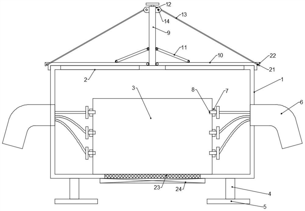
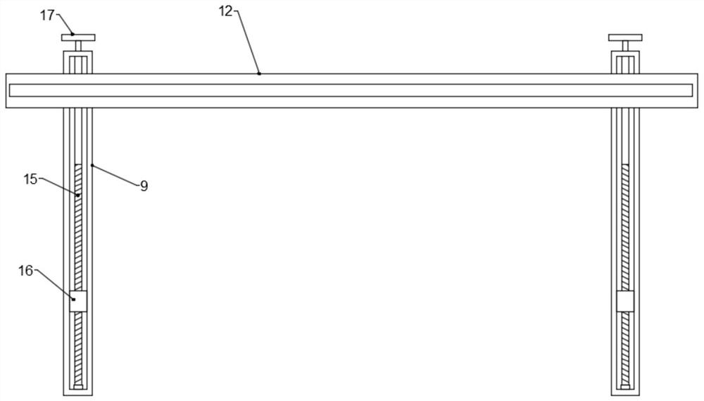
[0022] see figure 1 and 2 In the embodiment of the present invention, a cable connection box for a power distribution cabinet includes an outer box body 1 and two guide channels 6 arranged on the side walls of the outer box body 1. It is characterized in that the outer box body 1 is internally provided There is a cable connection seat 3 and the top wall of the outer box 1 is provided with two top access openings 2 symmetrical in the middle, and each top access opening 2 is provided with an upper cover 10 hinged on one side and one side. Two vertical cylinders 9 are arranged between the top inspection openings 2 and two winding cylinders 12 are arranged between the tops of the two vertical cylinders 9. The inside of the vertical cylinder 9 is provided with a flip wire whose ends are rotatably connected to it. The rod 15 and the flip screw 15 are provided with a driving screw sleeve 16 which is screwed with it. The driving screw sleeve 16 is symmetrically arranged with two flip...

Embodiment 2

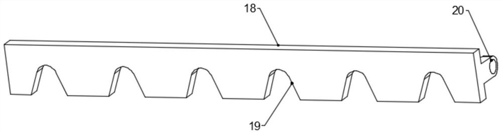
[0029] see figure 1 and 3 The difference between the embodiment of the present invention and the embodiment 1 is that: the side of the cable connection seat 3 facing the guide channel 6 is provided with a terminal connection row 7 having a plurality of connection terminals, and each terminal connection row 7 is outside Each is provided with a clip 8 for clamping the end of the cable. The clip 8 includes a horizontal bar 18 and side connecting parts 20 arranged at both ends of the horizontal bar 18. On the side wall, the lower side of the horizontal bar 18 is provided with a plurality of bayonet openings 19 corresponding to the plurality of connection terminals on the terminal connection row 7; The bayonet 19 clamps the tail of the cable connection end, so as to avoid loosening of the cable connection; the bayonet 19 is triangular in shape and its apex angle is an arc transition.


PUM


Abstract

The invention discloses a cable connection box for a power distribution cabinet, comprising an outer box body and two guide channels arranged on the side walls of the outer box body, and each top inspection opening is provided with an upper cover plate hinged on one side thereof. The top center of the top inspection port is provided with two vertical cylinders, and the top side walls of the two vertical cylinders are provided with two winding cylinders. The flip screw rod is provided with a driving screw sleeve that is screwed with it, the driving screw sleeve is provided with a flip cover push-pull rod hinged with it, the top of the flip screw rod is provided with an operating handwheel, and the inside of the winding cylinder is provided with a pass-through end portion. The roll is rotatably connected with the torsion spring, and the roll is wound with a rain cover, and one end of the rain cover is connected to the end of the upper cover plate away from the vertical cylinder through a connecting assembly. The invention has a simple structure, is convenient for the inspection of the flip cover, and uses the roll cover to prevent rain, and the roll cover is rolled up when the cover is flipped, so that the roll cover is well protected from rain and has strong practicability.

Description

technical field [0001] The invention relates to the technical field of power distribution boxes, in particular to a cable connection box for power distribution cabinets. Background technique [0002] Power distribution cabinets (boxes) are divided into power distribution cabinets (boxes), lighting distribution cabinets (boxes), and metering cabinets (boxes), which are the final equipment of the power distribution system. The power distribution cabinet is the general name of the motor control center. The power distribution box is an effective accessory in electrical equipment. Generally, switchgear, measuring instruments, protective appliances and auxiliary equipment need to be assembled in a closed or semi-closed metal cabinet, which can be used in normal operation. The circuit is turned on or off with the help of manual or automatic switches, but in the use of some power distribution cabinets that require special wiring, the cables enter the interior of the power distributi...

Claims


Application Information

Patent Timeline
Patent Type & Authority Patents(China)
IPC IPC(8): H02G3/08H02G3/14H02G3/16H02B1/28H02B1/30
CPCH02G3/088H02G3/14H02G3/16H02B1/28H02B1/30
Inventor 杨星强
Owner 恒凯电力设备有限公司
Why Eureka
Try Eureka