
Systems and methods for image-guided navigation of percutaneously inserted devices

An image guidance and equipment technology, applied in the field of image guidance and navigation of medical equipment, can solve the problems of inability to provide real-time imaging, tracking and motion perception.

Pending Publication Date: 2021-04-09
TYCO HEALTHCARE GRP LP
View PDF0 Cites 0 Cited by
  • Summary
  • Abstract
  • Description
  • Claims
  • Application Information

AI Technical Summary

Problems solved by technology

Although CT provides high spatial resolution and good tissue contrast, allowing precise and safe biopsy needle placement, CT cannot provide real-time imaging, tracking, and motion perception

Method used


Image

  • Systems and methods for image-guided navigation of percutaneously inserted devices
  • Systems and methods for image-guided navigation of percutaneously inserted devices
  • Systems and methods for image-guided navigation of percutaneously inserted devices

Examples


Embodiment Construction

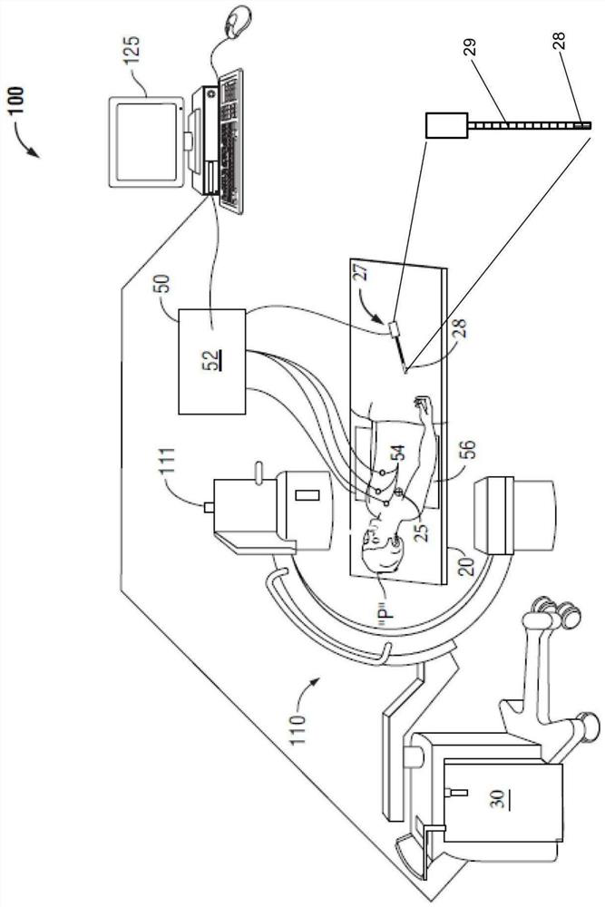
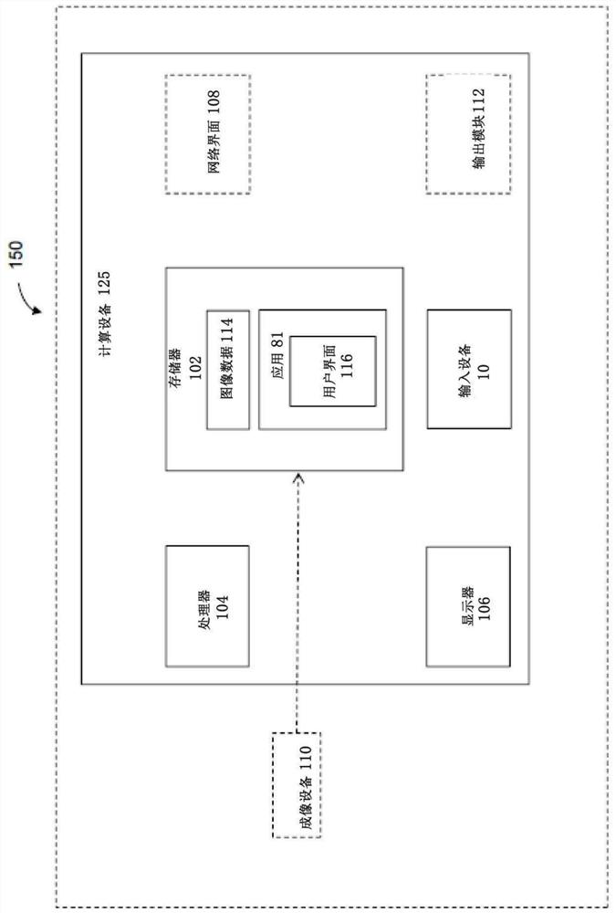
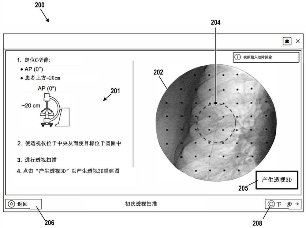
[0022]The present disclosure relates to systems and methods for image guidance, such as fluoroscopic scanning and / or (electromagnetic) EM guidance, navigation of percutaneously inserted devices, such as biopsy tools, therapeutic tools (such as ablation tools) or needles . An advantage of fluoroscopy is that fluoroscopy can provide a real-time view of medical procedures such as biopsy procedures. However, fluoroscopy may provide lower image quality than computed tomography (CT) images, which provide good visualization with axial and coronal views. One way to solve this problem is to fuse or merge the real-time fluoroscopic image with the CT image, for example by superimposing certain parts of the CT image on the fluoroscopic image and vice versa. For example, fusion can show a CT image around the tool in a perspective 3D reconstruction, because a CT image shows the pleura better than a perspective 3D reconstruction. Alternatively, fusion may include displaying the tool in a p...


PUM


Abstract

SYSTEMS AND METHODS FOR IMAGE-GUIDED NAVIGATION OF PERCUTANEOUSLY-INSERTED DEVICES. Systems and methods for image-guided medical procedures use fluoroscopic 3D reconstructions to plan and navigate a percutaneously-inserted device such as a biopsy tool from an entry point to a target.

Description

technical field [0001] This disclosure relates to the field of image-guided navigation of medical devices, and more particularly to image-guided navigation of percutaneously inserted tools from a percutaneous access point to a target (e.g., a tumor) to perform, for example, localization (e.g., using a dye, guide wire, or fiducial). ), biopsy, or targeted ablation procedures. Background technique [0002] Computed tomography (CT)-guided needle biopsy is a common method for obtaining tissue samples from lung nodules for lung cancer diagnosis. The patient lies on the CT table and receives an injection of local anesthetic to numb the needle path. Target lung nodules are located on preoperative CT scans, which clinicians can use to plan the safest needle path to target nodules. With the intraoperative CT scan confirming the location of the target nodule and the needle, the clinician inserts the needle into the skin, pushes it against the target nodule and enters the target nodu...

Claims


Application Information

Patent Timeline
IPC IPC(8): A61B34/20A61B6/12
CPCA61B34/20A61B6/12A61B6/52A61B2034/2051A61B2034/2065A61B2090/367A61B2090/376A61B2034/2048A61B2034/107A61B2090/3995A61B34/10A61B6/487A61B6/488A61B6/032A61B2090/3966G06T7/337G06T7/70A61B5/062A61B5/065A61B6/463A61B6/466A61B6/5205A61B6/5235A61B10/04A61B2010/045A61B2018/00577G06T11/003G06T2207/10081G06T2207/10121G06T2207/30004G06T2211/40
Inventor G·阿莱克斯安德罗尼O·P·维加藤E·科佩尔
Owner TYCO HEALTHCARE GRP LP
Learn More