Cutting equipment for mechanical arm meter bottom cover production

A technology of mechanical arm and bottom cover, which is applied in the field of material cutting equipment for the production of mechanical arm watch bottom cover, which can solve the problems of manual positioning, inconvenient blanking, troublesome operation, etc., and achieve fast clamping and positioning, convenient picking, and convenient The effect of retrieving

Inactive Publication Date: 2021-04-09
深圳市金三维实业有限公司
View PDF0 Cites 3 Cited by
  • Summary
  • Abstract
  • Description
  • Claims
  • Application Information

AI Technical Summary

Problems solved by technology

[0004] The purpose of the present invention is to solve the problem that when the existing mechanical watch bottom cover is stamped and formed, manual positioning is generally required when loading materials, which is troublesome to operate, and it is inc

Method used


Image

  • Cutting equipment for mechanical arm meter bottom cover production
  • Cutting equipment for mechanical arm meter bottom cover production
  • Cutting equipment for mechanical arm meter bottom cover production

Examples


Embodiment 1

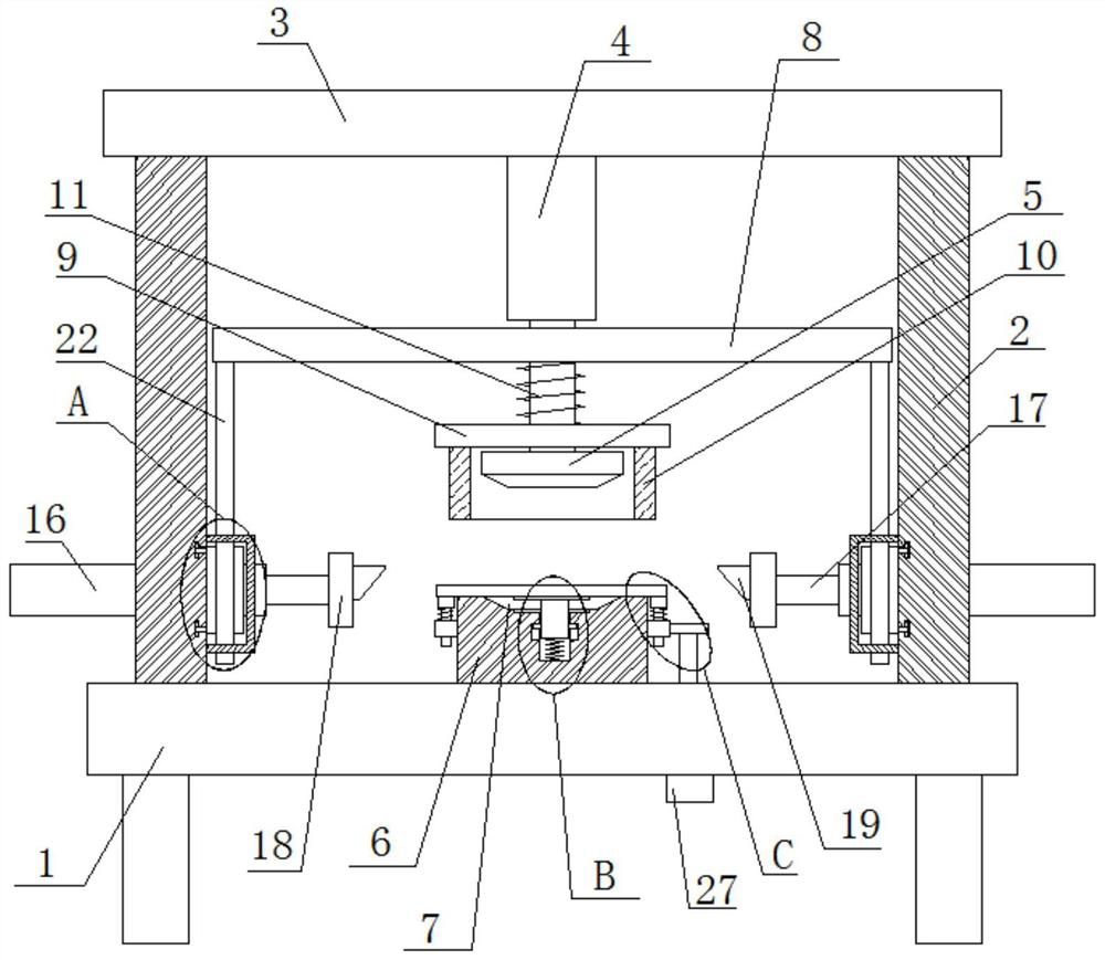
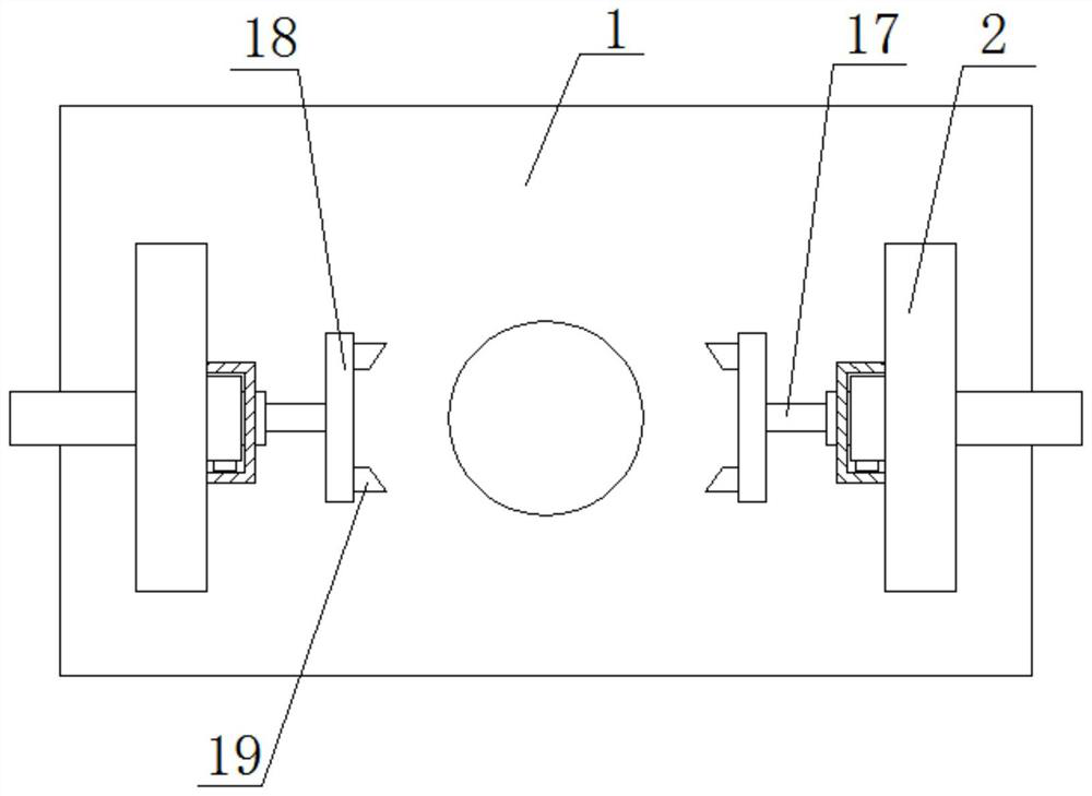
[0030] refer to Figure 1-7 , a kind of material cutting equipment for the production of mechanical arm table bottom cover, including an operation table 1, two symmetrically arranged support plates 2 are fixedly installed on the top of the operation table 1, and the same top plate 3 is fixedly installed on the top of the two support plates 2 , the bottom of the top plate 3 is fixedly equipped with a cylinder 4, the piston of the cylinder 4 is fixedly installed with an upper mold base 5, the top of the operating table 1 is fixedly installed with a lower mold base 6, and the top of the lower mold base 6 is provided with a mold groove 7, the mold A buffer groove 12 is provided on the bottom inner wall of the groove 7, a buffer rod 13 is slidably connected to the inner wall of the buffer groove 12, a buffer plate 14 is fixedly installed on the top of the buffer rod 13, and a buffer spring 15 is fixedly installed on the bottom end of the buffer rod 13, The bottom end of the buffer ...

Embodiment 2

[0040] refer to Figure 1-7 , a kind of material cutting equipment for the production of mechanical arm table bottom cover, including an operation table 1, two symmetrically arranged support plates 2 are welded on the top of the operation table 1, and the same top plate 3 is welded on the top of the two support plates 2, and the top plate The bottom of 3 is fixed with cylinder 4 by bolts, and upper mold base 5 is welded on the piston of cylinder 4, and lower mold base 6 is welded on the top of console 1, and the top of lower mold base 6 is provided with mold groove 7, and the mold groove 7 The bottom inner wall is provided with a buffer groove 12, and the inner wall of the buffer groove 12 is slidably connected with a buffer rod 13. The top of the buffer rod 13 is welded with a buffer plate 14, and the bottom end of the buffer rod 13 is welded with a buffer spring 15. end is fixedly connected with the inner wall of the buffer tank 12, a push rod 16 is slidably connected on the...


PUM


Abstract

The invention belongs to the technical field of cutting equipment, particularly relates to cutting equipment for mechanical arm meter bottom cover production, and provides the following scheme for solving the problems that when an existing mechanical meter bottom cover is subjected to punch forming, manual positioning is needed during general feeding, operation is troublesome, and feeding is inconvenient due to the fact that the bottom cover is embedded in a die groove during material taking. The equipment comprises an operation table, two symmetrically-arranged supporting plates are fixedly installed at the top of the operation table, the same top plate is fixedly installed at the tops of the two supporting plates, an air cylinder is fixedly installed at the bottom of the top plate, an upper die base is fixedly installed on a piston of the air cylinder, a lower die base is fixedly installed at the top of the operation table, a die groove is formed in the top of the lower die base, and a buffer groove is formed in the inner wall of the bottom of the die groove. The equipment is easy to operate and convenient to use, materials can be rapidly clamped and positioned, meanwhile, pressing and fixing can be conducted during stamping, material taking is convenient, and people can use the equipment conveniently.

Description

technical field [0001] The invention relates to the technical field of cutting equipment, in particular to a cutting equipment for the production of a watch bottom cover of a mechanical arm. Background technique [0002] Mechanical watches can generally be divided into the following two types: manual winding and self-winding watches. The power source of these two machines is powered by the mainspring in the movement, which drives the gear and then pushes the watch hands, but the way of power source is different. The mechanical watch that manual go up a chain is to rely on manual twist hair spring to make power, the thickness of machine core is a little thinner than the watch that go up automatically normally, relatively speaking the weight of the watch is just light. And the watch that go up a chain automatically, it is to use the automatic revolving disc of machine core to swing left and right to generate power to drive spring, but the thickness of the watch that go up a c...

Claims


Application Information

Patent Timeline
IPC IPC(8): B21D22/04F16F15/067B21D43/00B21D45/02B24B19/00B24B27/02B24B27/00B24B41/00B24B41/06
CPCB21D22/04B21D43/003B21D45/02B24B19/00B24B27/0046B24B27/02B24B41/007B24B41/06F16F15/067
Inventor 李铁球杨小梅
Owner 深圳市金三维实业有限公司
Why Eureka
Try Eureka