

Automatic charging device for sawing of rectangular pipes
An automatic feeding, rectangular tube technology, applied in the directions of transportation and packaging, conveyors, rollers, etc., can solve the problems of large position changes, unsuitable rectangular tubes, time-consuming, etc., to achieve accurate suction action, convenient and accurate suction. the effect of
- Summary
- Abstract
- Description
- Claims
- Application Information
AI Technical Summary
Problems solved by technology
Method used
Image

Examples
Embodiment Construction
[0031] The present invention will be described in further detail below through specific examples.
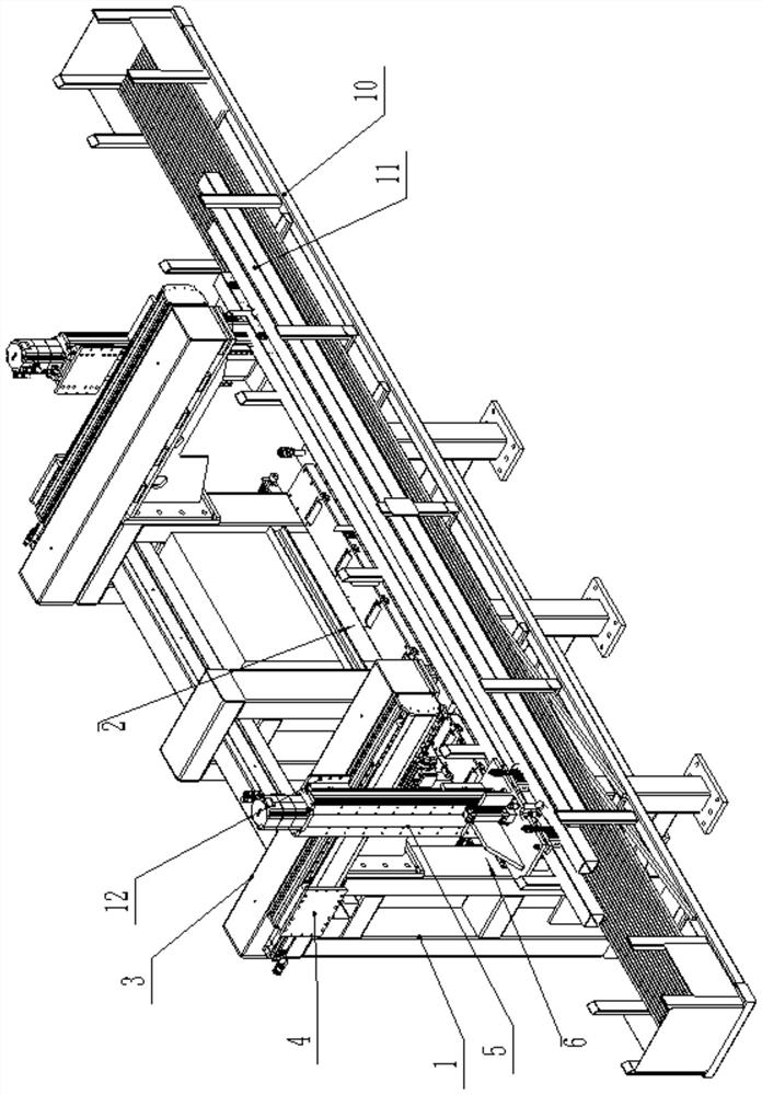
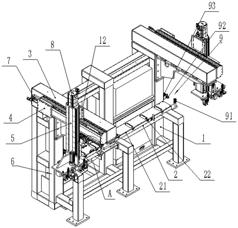
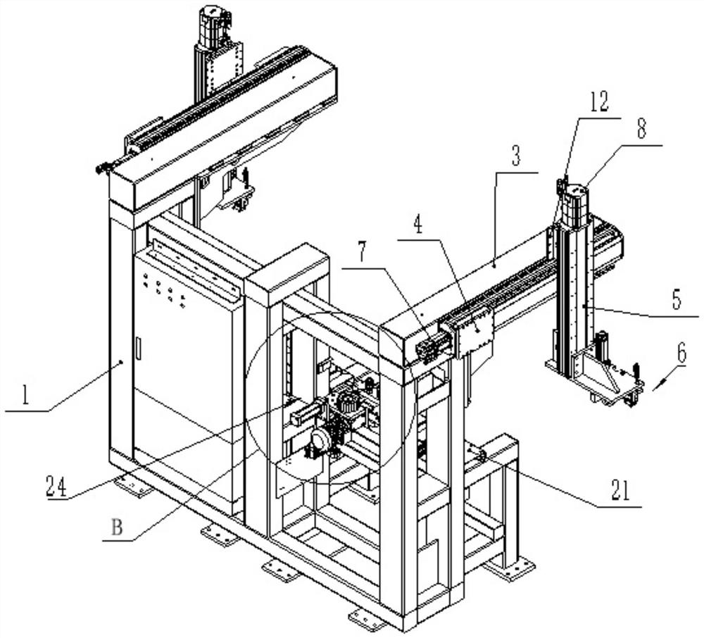
[0032] Such as Figure 1 to Figure 7 As shown, an automatic feeding device for sawing a rectangular tube 11, the automatic feeding device is arranged on one side of the raw material frame 10, including:
[0033] Frame 1; the frame 1 is used as the supporting carrier of the whole device, and the frame 1 is welded by steel structure.
[0034] Vertical conveying mechanism 2, described longitudinal conveying mechanism 2 is installed on the described frame 1 and is positioned on the conveying station, defines the position of raw material frame 10 as storage station;
[0035] Such as Figure 2 to Figure 5 As shown, the longitudinal conveying mechanism 2 includes a conveying platform 21 fixed on the frame 1, and several passive conveying rollers 22 are arranged at intervals on the conveying platform 21. In this embodiment, the passive conveying rollers 22 are rotatably installed on t...
PUM
 Abstract
Description
Claims
Application Information