Textile cutting device

A cutting device and textile technology, applied in the field of textiles, can solve problems such as difficult tool replacement, inability to remove wrinkles, and inability to change cutting shapes, etc., to achieve the effects of improving efficiency, not being prone to cracks, and improving stability

Pending Publication Date: 2021-04-09
韩文杰
View PDF6 Cites 0 Cited by
  • Summary
  • Abstract
  • Description
  • Claims
  • Application Information

AI Technical Summary

Problems solved by technology

[0006] In order to solve the technical problems existing in the background technology, the present invention proposes a textile cutting device, which solves th

Method used


Image

  • Textile cutting device
  • Textile cutting device
  • Textile cutting device

Examples


Embodiment 1

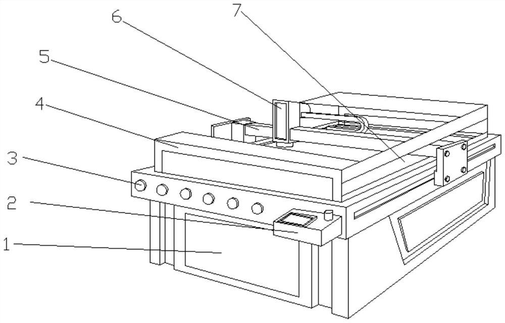
[0035]Such asFigure 1-3 One technical solution proposed in the present invention: a textile cutting device, including a base 1, a bottom fixed connection between the base 1, and the front side of the operating table 3 fixedly connected to the controller 2, the operation stage 3 The side is provided with a motor 5, and a cutting device 6 is provided on the top left side of the top portion of the mount 5, and the top portion of the operating table 3 is fixedly connected to the protective device 4, and the sidewall 7 is provided on both sides of the guard 4, and the middle of the mount 5 is run through. Slide 7.

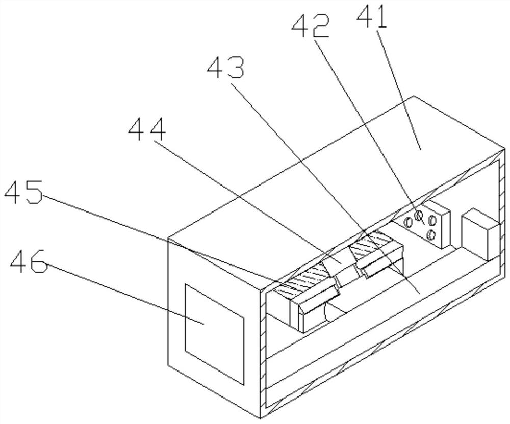
[0036]Wherein, the protective device 4 includes a frame 41, and a clamping mechanism 43 is provided with a clamping mechanism 43 in the front side of the outer casing 41, and the intermediate position of the outer casing 41 is fixed to the intermediate position of the separator 45, and the middle cavity of the separator 45 is provided. The support shaft 44, the intermediate posi...

Embodiment 2

[0040]Such asFigure 1-4 As shown, in the basis of the first example, the present invention provides a technical solution: the clamping mechanism 43 includes a bracket 434, and the middle portion of the front portion of the bracket 434 is opened, and the inner wall of the grip groove 435 is fixedly connected. There is a fixed teeth 436, and the top two sides of the bracket 434 are fixedly connected to the fixed block 431, and the lumen bottom of the fixing block 431 is fixedly coupled to the side slide 433, and the top portion of the side slide 433 is provided with a hosted frame 432.

[0041]When used, from the box door 46 is placed in the material, press the start button on the controller 2, the mount 5 drives the cutting device 6 on the operating table 3 by the chute 7, and the material is more vivid to the inside of the device. The case where the material cutting will be clamped, the box door 46 can perform the internal cleaning, the through hole 42 performs internal ventilation, ma...

Embodiment 3

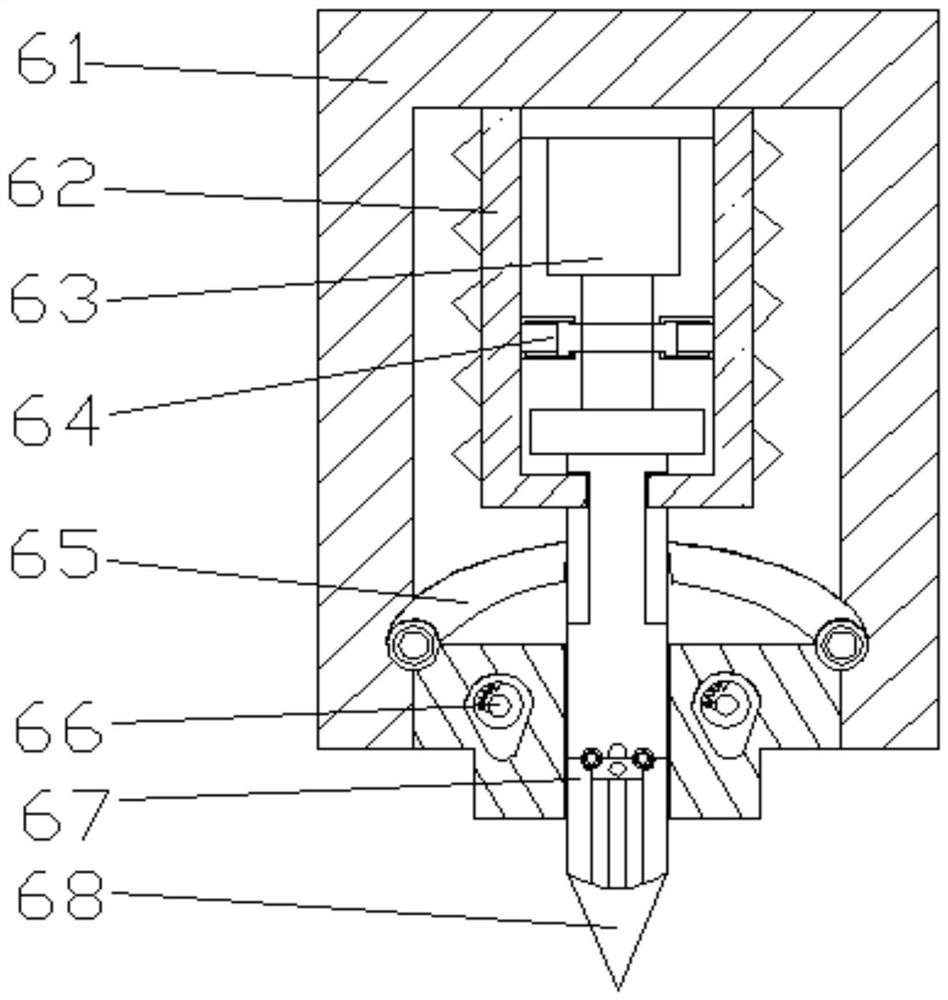
[0043]Such asFigure 1-6As shown, in the basis of the first embodiment, the present invention provides a technical solution: the drive mechanism 65 includes a bottom plate 652, and the top portion of the bottom plate 652 is fixedly connected to the upper plate 651, the bottom plate 652 is fixedly connected. There is a regulating mechanism 653, and the intermediate position of the bottom plate 652 is fixed to the outer extension rod 654, and the intermediate position of the outer extension rod 654 is fixedly connected to the pull block 655.

[0044]Wherein, the regulating mechanism 653 includes a carrier plate 6533, and the top portion of the carrier plate 6533 is provided with a swing block 6532, and the internal shrinkage block 6532 is provided. The upper left side of the swift block 6531 is provided with a front plate 6534, a swift block 6531 The contact ball 6535 is fixed to the position close to the front plate 6534.

[0045]When used, from the box door 46 is placed in the material, pr...


PUM


Abstract

The invention discloses a textile cutting device which comprises a base, wherein an operation table is fixedly connected to the bottom of the base, a controller is fixedly connected to the right side of the front face of the operation table, a driving frame is arranged on two sides of the operation table, a cutting device is arranged on the left side of the top of the driving frame, a protection device is fixedly connected to the top of the operation table, sliding grooves are formed in two sides of the protection device, and the sliding grooves penetrate through the middle of the driving frame. The invention relates to the technical field of textiles. According to the textile cutting device, through arrangement of the protection device, the cutting device and the operation table, the cutting device conducts cutting on the operation table, and a gap is formed between a cutter and the operation table during cutting, so that scratches on the operation table caused by the cutter are avoided; through arrangement of the driving frame, the cutting shape can be conveniently changed during cutting, the cutter can be conveniently replaced, wrinkles can be removed, and thus the cutter is prevented from being damaged in a lifting process, and the support of the cutter is further increased.

Description

Technical field[0001]The present invention relates to the field of textile technology, and more particularly to a textile cutting device.Background technique[0002]Textile origin is the general name of the spinning and weaving, but with the continuous development and improvement of the textile knowledge system and the discipline system, especially the nonwoven textile materials and three-dimensional compound weaving, the current textile is not only a traditional Handmade spinning and weaving, including non-woven technology, modern three-dimensional knitting technology, modern electrostatic nanoma technology, etc., industrial, decorated textiles.[0003]According to a cutting device disclosed in China Patent No. CN11155296A, a cloth roll can be fixed to the fixed bar by setting a fixed frame, a press plate and a sheet roller, and the fabric that needs to be cut through the mounting frame through the first The three electric telescopic rod pushes the movable seat, the upper roller is pre...

Claims


Application Information

Patent Timeline
IPC IPC(8): D06H7/00
CPCD06H7/00
Inventor 韩文杰
Owner 韩文杰
Why Eureka
Try Eureka