Head shaking structure and air inducing device

A technology of driving device and handpiece, which is applied to pump devices, components of pumping devices for elastic fluids, non-variable-capacity pumps, etc., can solve the problems of low stability, complicated structure of shaking head, etc., and achieve simple assembly. , The effect of direct driving mode and reliable structure

Inactive Publication Date: 2021-04-09
GREE ELECTRIC APPLIANCES INC
View PDF0 Cites 1 Cited by
  • Summary
  • Abstract
  • Description
  • Claims
  • Application Information

AI Technical Summary

Problems solved by technology

[0003] Therefore, the technical problem to be solved by the present invention is to overcome the defects of complex structure and low stability of the oscillating head structure in the prior art, thereby providing a oscillating head structure with a relatively simple structure and high stability.
[0004] Another technical problem to be solved by the present invention is to overcome the defects of complex structure and low stability of the swing head in the prior art, so as to provide a relatively simple structure and high stability of the wind induction device

Method used


Image

  • Head shaking structure and air inducing device
  • Head shaking structure and air inducing device
  • Head shaking structure and air inducing device

Examples


Embodiment 1

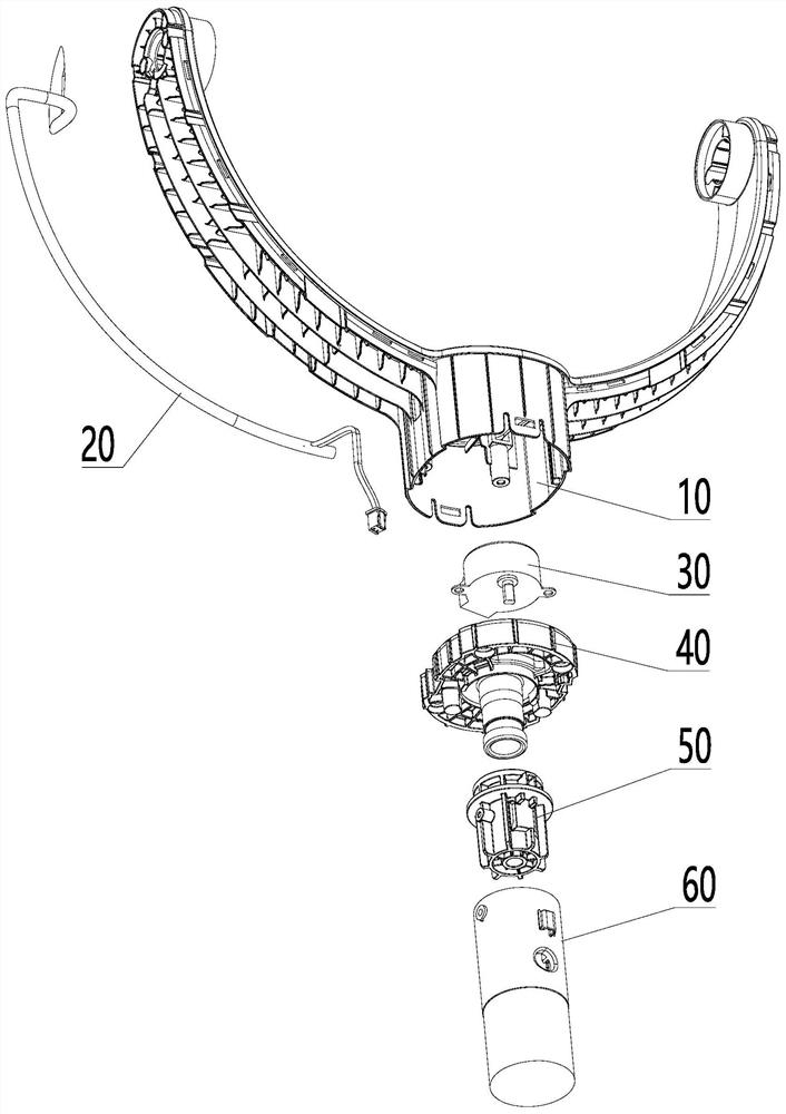
[0066] combine Figure 1-Figure 12 As shown, the shaking head structure provided by this embodiment includes:

[0067] Head support 10;

[0068] drive means 30;

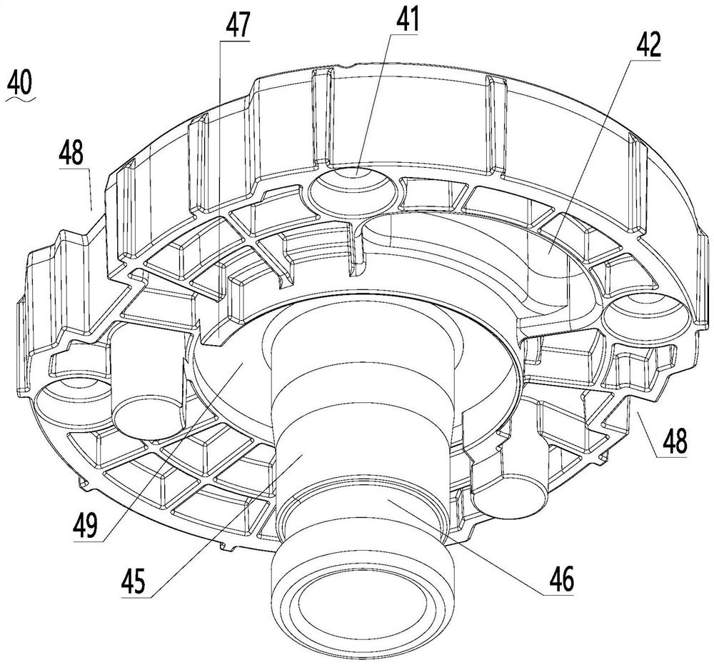
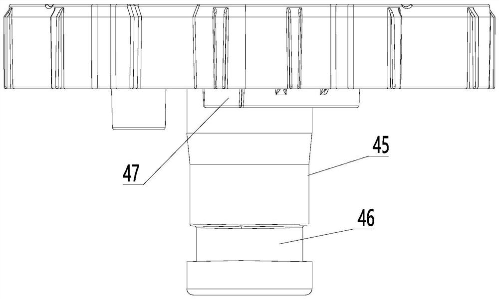
[0069] The driving device fixing plate 40 is adapted to fix the driving device 30 and be fixedly connected with the head support 10; and

[0070] The assembly support member 50 is installed in cooperation with the drive shaft of the drive device 30 , and under the driving force of the drive device 30 , the drive device fixing plate 40 and the assembly support member 50 are relatively rotated.

[0071] The driving device 30 described in this embodiment is used to drive the fixing plate 40 of the driving device and the assembly supporting member 50 to rotate relative to each other. Preferably, the drive device 30 may specifically be a motor, or a component in which the motor drives a gear structure to move, or a component in which a motor drives a belt to move, or a cylinder drives a crank connecting rod mechanism, ...

Embodiment 2

[0119] This embodiment provides an air induction device, including: the above-mentioned oscillating structure, and

[0120] The installation pipe 60 is fixedly connected with the assembly support member 50 of the swinging head structure.

[0121] The installation tube 60 and the assembly support 50 are provided with screw holes correspondingly, and the installation tube 60 and the assembly support 50 are fixed by screws.

[0122] After the assembly support 50 is fixed, if the installation tube 60 is in a fixed state in use, the assembly support 50 also remains different. At this time, when the driving device 30 operates, the The fixing plate 40 of the driving device rotates relative to the assembly support member 50 , so that the fixing plate 40 of the driving device rotates relative to the ground, drives the head bracket 10 to rotate, and makes the fan shake its head.

[0123] Preferably, the air-inducing device can be used for blowing or sucking air according to the differe...


PUM


Abstract

The invention relates to the technical field of fans, in particular to a head shaking structure and an air inducing device. The head shaking structure comprises a machine head support, a driving device, a driving device fixing plate suitable for fixing the driving device and fixedly connected with the machine head support and an assembling supporting piece, wherein the assembling supporting piece and a driving shaft of the driving device are mounted in cooperation, and under the driving force of the driving device, the driving device fixing plate and the assembling supporting piece rotate relatively. According to the head shaking structure, the driving device fixing plate is fixedly connected with the driving device and the machine head support, the driving device fixing plate and the assembling supporting piece are driven by the driving device to rotate relatively, and therefore the machine head support is driven to rotate, and the head shaking effect is achieved; and the assembling supporting piece is directly driven by the driving device, under the counter-acting force, a driving device machine body, the driving device fixing plate and the machine head support rotate synchronously, the driving manner is direct, assembling is easy, and the structure is reliable.

Description

technical field [0001] The invention relates to the technical field of fans, in particular to an oscillating head structure and an air induction device. Background technique [0002] As a household appliance commonly used in summer, electric fans usually include the working mode of swinging the head to supply air. At present, the swinging head structure generally adopts the linkage mechanism and the gear transmission structure in the market. However, the swinging head structure using the linkage mechanism often has complex structures, There are disadvantages such as low stability, and the oscillating head structure using gear transmission has problems such as complex structure and high cost. Contents of the invention [0003] Therefore, the technical problem to be solved by the present invention is to overcome the defects of complicated structure and low stability of the oscillating head structure in the prior art, so as to provide an oscillating head structure with a rela...

Claims


Application Information

Patent Timeline
IPC IPC(8): F04D25/10F04D29/00F04D29/64F04D29/054
CPCF04D25/105F04D29/002F04D29/054F04D29/646
Inventor 王勇冯爽申志强王季彦范瑞鹏
Owner GREE ELECTRIC APPLIANCES INC
Why Eureka
Try Eureka