Liquid nitrogen dumping device and dumping method thereof

A technology of pouring device and liquid nitrogen, which is applied in container filling method, container discharging method, container structure installation device, etc., can solve the problems of high operational risk factor, low work efficiency, high labor intensity, etc., and reduce safety risks. , the effect of reduced labor intensity and strong applicability

Inactive Publication Date: 2021-04-09
CHONGQING TIEMA IND GRP
View PDF9 Cites 2 Cited by
  • Summary
  • Abstract
  • Description
  • Claims
  • Application Information

AI Technical Summary

Problems solved by technology

The original operation method is to manually pour liquid nitrogen into the bucket, which is labor-intensive and low-efficiency. It is easy to frostbite during the process of pouring liquid nitrogen, and the operation risk factor is high.

Method used


Image

  • Liquid nitrogen dumping device and dumping method thereof
  • Liquid nitrogen dumping device and dumping method thereof

Examples


Embodiment 1

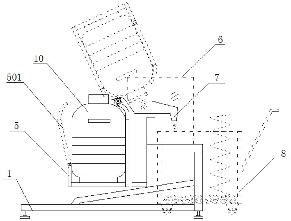
[0026] This embodiment discloses a liquid nitrogen pouring device, see figure 1 and figure 2 , the dumping device includes a frame 1, a driving mechanism, a rotating shaft 4, a liquid nitrogen tank hoop locking mechanism 5, a plexiglass protective cover 6 and a liquid nitrogen funnel 7.

[0027] The frame 1 is equipped with a controller 9 . The frame 1 has a driving mechanism installation platform and a rotating shaft support frame 101 .

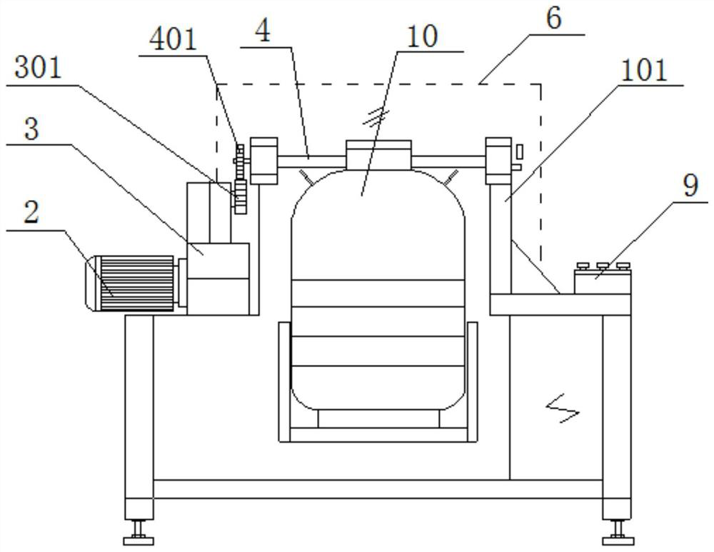
[0028] The rotating shaft 4 is rotatably installed on the rotating shaft supporting frame 101 . The drive mechanism includes a geared motor 2 and a worm gear reducer 3 .

[0029] The geared motor 2 is fixed on the drive mechanism installation platform of the frame 1 . The controller 9 is connected to the geared motor 2, and controls the forward rotation and reverse rotation of the geared motor 2 through the controller 9.

[0030] The worm gear reducer 3 is fixed on the drive mechanism installation platform of the frame 1 , and the inpu...

Embodiment 2

[0039] This embodiment provides a relatively basic implementation, a liquid nitrogen pouring device, see figure 1 and figure 2 , including a frame 1, a driving mechanism, a rotating shaft 4, a liquid nitrogen tank hoop locking mechanism 5 and a liquid nitrogen funnel 7.

[0040] The frame 1 has a driving mechanism installation platform and a rotating shaft support frame 101 .

[0041] The rotating shaft 4 is rotatably installed on the rotating shaft supporting frame 101 .

[0042] The drive mechanism is fixed on the drive mechanism installation platform. The drive mechanism drives the rotating shaft 4 to rotate.

[0043] The hoop locking mechanism 5 of the liquid nitrogen tank is a square shell as a whole, the lower end of which is closed, and the upper end is bent inward to form a constriction. A side wall of the hoop locking mechanism 5 for the liquid nitrogen tank is provided with an openable and closable pressing plate 501, the lower end of the pressing plate 501 is h...

Embodiment 3

[0047] The main steps of this embodiment are the same as those of Embodiment 2, further, the drive mechanism includes a reduction motor 2 and a worm gear reducer 3 .

[0048] The geared motor 2 is fixed on the drive mechanism installation platform of the frame 1 . The controller 9 is connected to the geared motor 2, and controls the forward rotation and reverse rotation of the geared motor 2 through the controller 9.

[0049] The worm gear reducer 3 is fixed on the drive mechanism installation platform of the frame 1 , and the input end of the worm gear reducer 3 is connected to the output shaft of the reduction motor 2 . A drive gear 301 is fixedly connected to the output shaft of the worm gear reducer 3 .

[0050] A driven gear 401 is fixedly connected to the end of the rotating shaft 4 . The driven gear 401 meshes with the driving gear 301 .


PUM


Abstract

The invention discloses a liquid nitrogen dumping device and a dumping method thereof. The dumping device comprises a rack, a driving mechanism, a rotating shaft, a liquid nitrogen tank hoop locking mechanism and a liquid nitrogen funnel; a driving mechanism mounting platform and a rotating shaft supporting frame are arranged on the rack; the rotating shaft is mounted on the rotating shaft supporting frame; the driving mechanism is mounted on the driving mechanism mounting platform; the driving mechanism drives the rotating shaft to rotate; the upper end of the liquid nitrogen tank hoop locking mechanism is fixedly connected to the rotating shaft; and the liquid nitrogen funnel is installed on the rack, and when the driving mechanism drives the rotating shaft to rotate, the rotating shaft drives the liquid nitrogen tank hoop locking mechanism to rotate, so that a necking opening in the upper end of the liquid nitrogen tank hoop locking mechanism corresponds to the liquid nitrogen funnel. According to the liquid nitrogen dumping device, rapid clamping of a liquid nitrogen bottle can be achieved through the dumping device, liquid nitrogen is automatically and stably poured into a liquid nitrogen container, and the method is easy to operate, high in reliability, high in applicability and free of potential safety hazards.

Description

technical field [0001] The invention belongs to the field of liquid nitrogen cooling assembly for armored vehicles, and in particular relates to a liquid nitrogen dumping device and a dumping method thereof. Background technique [0002] Since the guide device of the armored vehicle suspension system is assembled with an interference fit with the steering knuckle, the guide device needs to be cooled with liquid nitrogen before assembly, so that the guide device can be cooled and shrunk before the assembly can be completed. Liquid nitrogen is a colorless liquid that is stored in a pressure-resistant steel cylinder. When cooling the guide device, it is necessary to pour the liquid nitrogen in the liquid nitrogen bottle into the liquid nitrogen bucket first, and then put the guide device into the liquid nitrogen bucket to cool. During the process of pouring liquid nitrogen, the liquid nitrogen will absorb a lot of heat when it vaporizes, and skin contact will cause frostbite. ...

Claims


Application Information

Patent Timeline
Patent Type & Authority Applications(China)
IPC IPC(8): F17C1/00F17C7/02F17C13/00F17C13/08
CPCF17C1/00F17C7/02F17C13/00F17C13/08F17C2201/0109F17C2201/032F17C2205/0153F17C2221/014F17C2223/013F17C2227/046
Inventor 彭赞余林徐立志张洋陈家宝王丽娜张海荣李骥刘志杰
Owner CHONGQING TIEMA IND GRP
Why Eureka
Try Eureka