Air conditioning unit control method and device and air conditioning unit

An air-conditioning unit and control method technology, which is applied to heating and ventilation control systems, refrigerators, heating methods, etc., can solve the problems of poor reliability and low energy efficiency of evaporative cooling units, and achieve the purpose of avoiding icing, improving reliability, and improving refrigeration. The effect of energy efficiency

Pending Publication Date: 2021-04-09
GREE ELECTRIC APPLIANCES INC
View PDF6 Cites 0 Cited by
  • Summary
  • Abstract
  • Description
  • Claims
  • Application Information

AI Technical Summary

Problems solved by technology

[0004] The present invention provides an air conditioning unit control method, device and air conditioning unit to at least solve the problems of low energy efficiency and poor reliability of evaporative cooling units in the prior art

Method used


Image

  • Air conditioning unit control method and device and air conditioning unit
  • Air conditioning unit control method and device and air conditioning unit
  • Air conditioning unit control method and device and air conditioning unit

Examples


Embodiment 1

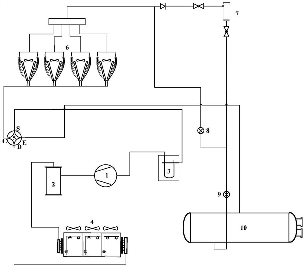
[0023] In the preferred embodiment 1 of the present invention, a control method of an air conditioning unit is provided, which can be directly applied to an evaporative cooling unit, figure 1 An optional schematic diagram showing the structure of the evaporative cooling unit, such as figure 1 As shown, it includes: compressor 1, oil separator 2, vapor-liquid separator 3, evaporative condenser 4, four-way reversing valve 5, finned condenser 6, plate heat exchanger 7, electronic expansion valve-8 , electronic expansion valve II 9, shell and tube evaporator 10.

[0024] During the refrigeration or heating cycle, the flow path of the refrigerant is as follows:

[0025] (1) When cooling in summer, the refrigerant flow path is: compressor 1—oil separator 2—evaporative condenser 4—four-way reversing valve 5—fin condenser 6—dryer 7—electronic expansion valve 2 9 — Shell and tube evaporator 10 — Four-way reversing valve 5 — Vapor-liquid separator 3 — Compressor 1.

[0026] (2) When ...

Embodiment 2

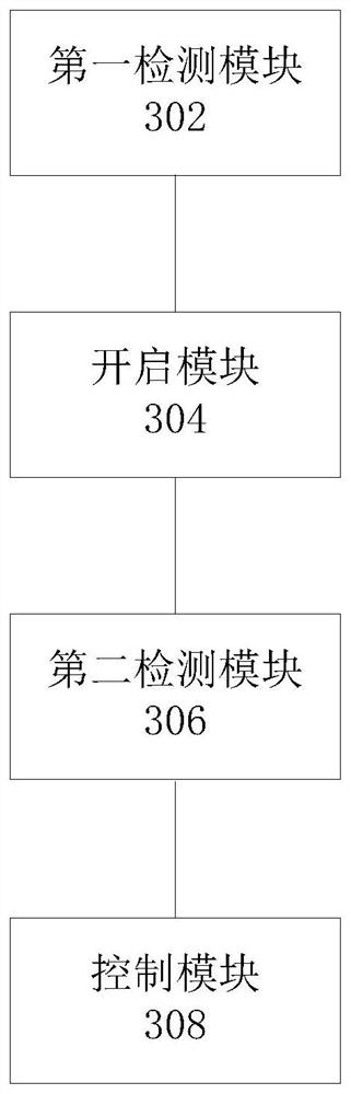
[0051] Based on the air-conditioning unit control method provided in the above-mentioned embodiment 1, an air-conditioning unit control device is also provided in preferred embodiment 2 of the present invention, specifically, image 3 shows an optional structural block diagram of the device, such as image 3 As shown, the device includes:

[0052] The first detection module 302 is used to detect the operation mode of the air conditioning unit;

[0053] The opening module 304 is used to control the opening of the condenser according to the operation mode;

[0054] The second detection module 306 is used to detect the chilled water outlet temperature of the condenser;

[0055] The control module 308 is used for controlling the operation of the compressor and the condenser according to the chilled water outlet temperature.

[0056] In the above-mentioned embodiment, components such as finned heat exchangers are added to the existing single-cooling evaporative cooling unit, and...

Embodiment 3

[0059] Based on the air-conditioning unit control device provided in the above-mentioned embodiment 2, an air-conditioning unit is also provided in preferred embodiment 3 of the present invention, including the above-mentioned air-conditioning unit control device.

[0060] In the above-mentioned embodiment, components such as finned heat exchangers are added to the existing single-cooling evaporative cooling unit, and corresponding controls are used to make the evaporative cooling unit meet the heating demand in winter, which can not only effectively avoid evaporative condensation in winter It can also improve the cooling energy efficiency under high temperature and high humidity conditions, and further improve the reliability of the unit.


PUM


Abstract

The invention discloses an air conditioning unit control method and device and an air conditioning unit. The air conditioning unit is an evaporative refrigerating unit, and condensers of the air conditioning unit comprise an evaporative condenser and a fin condenser. The method comprises the steps that the operation mode of the air conditioning unit is detected; the corresponding condenser is controlled to be started according to the operation mode; the chilled water outlet temperature of the condenser is detected; and the operation of a compressor and the condenser is controlled according to the chilled water outlet temperature. By means of the method, the problems of low energy efficiency and poor reliability of an evaporative refrigerating unit in the prior art are solved, and the energy efficiency and reliability of the air conditioning unit are improved.

Description

technical field [0001] The present invention relates to the technical field of air conditioning, in particular, to an air conditioning unit control method and device, and the air conditioning unit. Background technique [0002] With the acceleration of urbanization, rail transit is being built everywhere. These places have a large flow of people and a large space, which requires huge energy consumption to maintain the comfort of the internal environment of the building. Air-cooled units have low energy efficiency and high energy consumption. Although water-cooled units have high energy efficiency, they need to be equipped with corresponding cooling towers, which occupy a large area and are not easy to install and maintain. Traditional air-cooled units and water-cooled units can no longer meet the demand. Evaporative cooling units come into being. Health, can better meet the needs of the market. However, most of the current evaporative cooling units are single-cooling units,...

Claims


Application Information

Patent Timeline
Patent Type & Authority Applications(China)
IPC IPC(8): F24F11/86F24F11/67F25B39/04F25B49/02F24F140/20
CPCF25B39/04F25B49/022F25B2339/041F25B2600/021F24F11/67F24F11/86F24F2140/20
Inventor 卓明胜张丹丹刘洋陈培生
Owner GREE ELECTRIC APPLIANCES INC
Why Eureka
Try Eureka