Aero-engine birotor-support-casing tester and testing method thereof

An aero-engine, dual-rotor technology, applied in the testing of machine/structural components, mechanical components, static/dynamic balance testing, etc., can solve the problems of many influencing factors, simplified model differences, complex structure of aero-real engines, etc. , to achieve the effect of comprehensive consideration and rational structure simplification

Pending Publication Date: 2021-04-09
韩清凯
View PDF6 Cites 8 Cited by
  • Summary
  • Abstract
  • Description
  • Claims
  • Application Information

AI Technical Summary

Problems solved by technology

[0003] The internal rotor and support structure of the aero-engine are complex, and the existing test methods cannot directly obtain the vibration data of the rotor structure body on the real engine; numerical simulation and simulation technology cannot determine the internal vibration state data of the aero-engine with high precision, and it is even more difficult to accurately Analyze the law of the internal rotor vibration of the engine being transmitted to the outside and the final vibration performance on the external measuring point
[0004] The structure of the real aviation engine is complex, and there are many influencing factors, so the experimental research of the aircraft engine is limited; most of the development of the domestic rotor tester adopts the structural form of the rigid support of the disc shaft, and does not consider the disc-drum coupling structure and the elastic support to the rotor. The influence of vibration characteristics, the simplified model is very different from the structure of the real machine, and cannot simulate the vibration characteristics of the real engine well

Method used


Image

  • Aero-engine birotor-support-casing tester and testing method thereof
  • Aero-engine birotor-support-casing tester and testing method thereof
  • Aero-engine birotor-support-casing tester and testing method thereof

Examples


Embodiment Construction

[0054] The technical solutions in the embodiments of the present invention will be clearly and completely described below in conjunction with the drawings in the present invention. Apparently, the described embodiments are only some of the embodiments of the present invention, not all of them. Based on the embodiments of the present invention, all other embodiments obtained by persons of ordinary skill in the art without making creative efforts belong to the protection scope of the present invention.

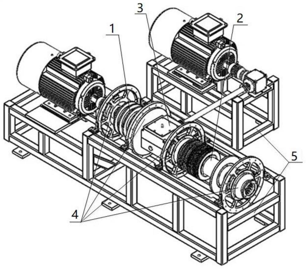
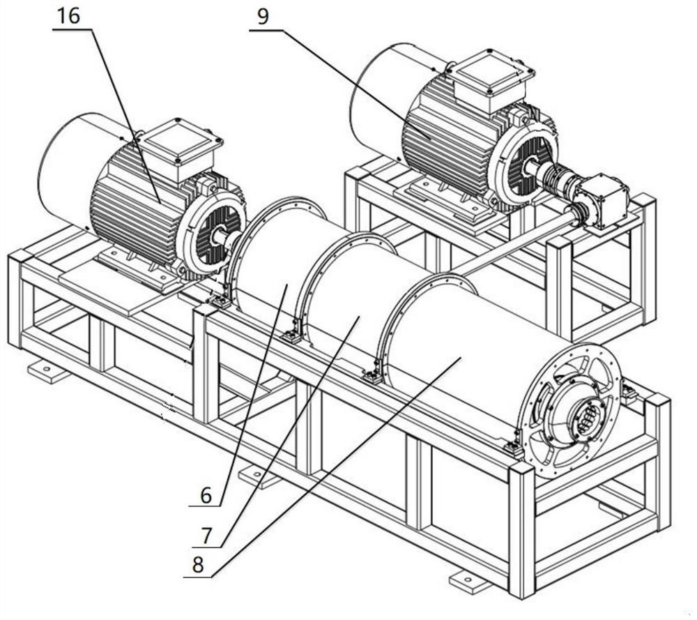
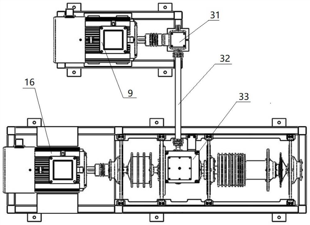
[0055] Such as Figures 1 to 3 As shown, the present invention provides an aero-engine double rotor-support-casing tester, comprising a low-pressure rotor 1, a central bevel gear system 3 and a high-pressure rotor 2 arranged laterally in sequence, wherein: the low-pressure rotor 1, the central bevel gear system 3 and the high-pressure rotor 2 are fixed on the frame 5 through the support structure 4, the outer periphery of the low-pressure rotor 1 is arranged with a low-pressure ...


PUM


Abstract

The invention belongs to the technical field of aero-engine testing and testing, and particularly relates to an aero-engine birotor-support-casing tester and a testing method thereof. The aero-engine birotor-support-casing tester comprises a low-pressure rotor, a central bevel gear system, a high-pressure rotor, a low-pressure casing, a middle casing and a high-pressure casing; the low-pressure rotor comprises a low-pressure turbine shaft, and the low-pressure turbine shaft penetrates through the central bevel gear system and is rotationally connected with the high-pressure rotor; and the low-pressure rotor is driven by a low-pressure driving motor, the central bevel gear system is connected with a high-pressure driving motor, and the high-pressure rotor is driven by the central bevel gear system. The structure is simplified and reasonable, the scale design with the fixed proportion (such as 2: 1) is adopted according to the real engine structure, and the four-stage fan disc and the nine-stage high-pressure disc are consistent with the real engine structure. Structures such as a squirrel cage, a conical shell, a bearing spoke plate and a flexible casing in a real machine are reserved, the structure and vibration of an engine rotor system can be truly simulated, and the whole machine vibration research requirement of an aero-engine is met.

Description

technical field [0001] The invention belongs to the technical field of aero-engine testing and testing, in particular to an aero-engine double-rotor-support-casing tester and a testing method thereof. Background technique [0002] With the increase of the thrust-to-weight ratio of the aero-engine, the structure of the rotor system changes greatly, and the high speed of the aero-engine makes the vibration problem of the aero-engine more prominent. Aeroengine rotor dynamics coupling characteristics, rotor unbalanced vibration transmission, including the vibration transmission law of aero-engine internal transmission and external transmission, and the influence of hanging point on vibration transmission, disk-drum coupling vibration characteristics, gear meshing excitation, etc. The influence of vibration and the vibration law of the casing are more complicated, and there are many unclear points in the mechanism and law, which need to be studied urgently. In particular, after ...

Claims


Application Information

Patent Timeline
Patent Type & Authority Applications(China)
IPC IPC(8): G01M13/00G01M1/16G01H17/00
CPCG01M13/00G01M1/16G01H17/00
Inventor 韩清凯韩朔王平张涛卢崇劭温保岗张旭方
Owner 韩清凯
Why Eureka
Try Eureka