Earphone system and microphone device thereof
A technology for microphones and earphones, which can be used in earpiece/earphone accessories, earphones to reduce environmental noise, frequency/direction characteristic devices, etc. It can solve problems such as the volume limit of the shock-absorbing structure, and achieve the effect of improving the call effect
- Summary
- Abstract
- Description
- Claims
- Application Information
AI Technical Summary
Problems solved by technology
Method used
Image
Examples
Embodiment 1
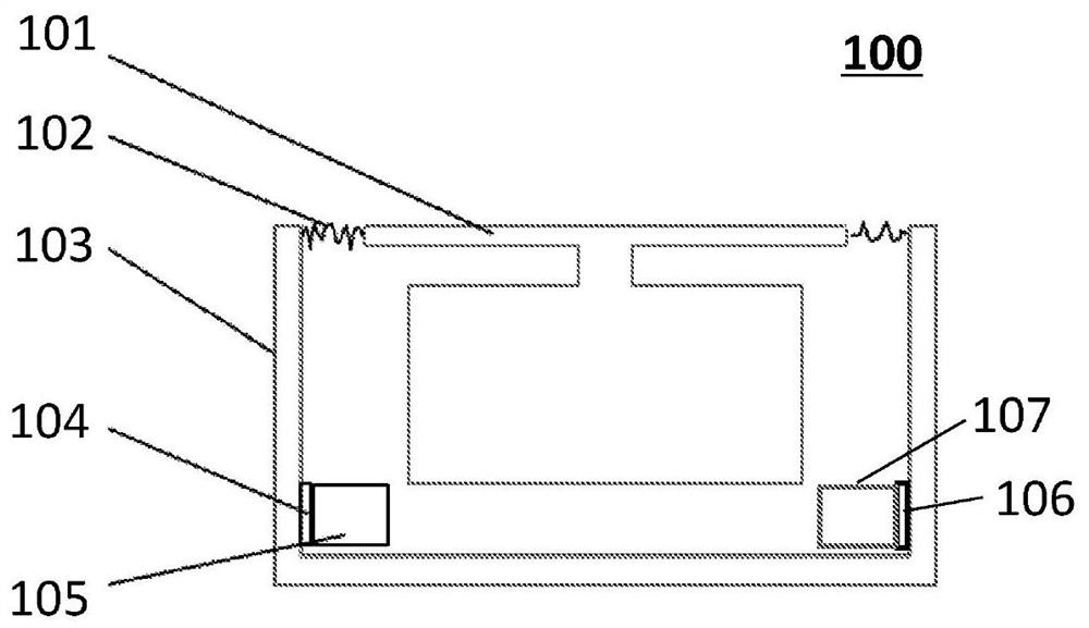
[0084] Such as Figure 16 As shown, the earphone 1600 includes an air conduction microphone 1601 , a bone conduction microphone 1602 and a housing 1603 . Wherein, the sound inlet hole 1604 of the air conduction microphone 1601 communicates with the air outside the earphone 1600 , and the side of the air conduction microphone 1601 is connected to the side of the shell 1603 . A bone conduction microphone 1602 is glued on one side inside the housing 1603 . The air-conduction microphone 1601 can obtain an air-conduction voice signal through the sound inlet 1604 , and obtain a first vibration signal (ie, a vibration noise signal) through the connection structure between the side and the housing 1603 . The bone conduction microphone 1602 can acquire the second vibration signal (ie, the mechanical vibration signal transmitted by the housing 1603 ). Both the first vibration signal and the second vibration signal are generated by the vibration of the housing 1603 . In particular, si...
Embodiment 2
[0086] Such as Figure 17 As shown, a dual microphone assembly 1700 includes an air conduction microphone 1701 , an enclosed microphone 1702 and a housing 1703 . Wherein, the air conduction microphone 1701 and the closed microphone 1702 are integral components, and the outer walls of the two microphones are bonded to the inner side of the shell 1703 respectively. The sound inlet 1704 of the air conduction microphone 1701 communicates with the air outside the dual microphone assembly 1700, and the sound inlet 1702 of the closed microphone 1702 is located at the bottom of the air conduction microphone 1701 and kept isolated from the outside air (equivalent to Figure 9-B closed microphone in ). In particular, the closed microphone 1702 can use the same air conduction microphone as the air conduction microphone 1701, and the closed form of the closed microphone 1702 is not communicated with the outside air through structural design. This one-piece structure makes the air conduc...
Embodiment 3
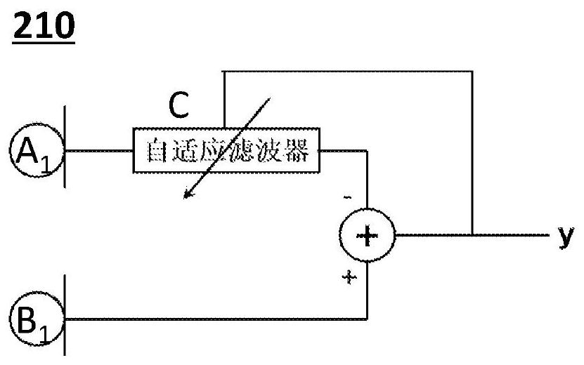
[0089] Figure 19 is a schematic diagram of a dual-microphone headset structure. Such as Figure 19 As shown, the earphone 1900 includes a vibration speaker 1901 , a housing 1902 , an elastic element 1903 , an air conduction microphone 1904 , a bone conduction microphone 1905 and an opening 1906 . Wherein, the vibration speaker 1901 is fixed on the shell 1902 through the elastic element 1903 . The air conduction microphone 1904 and the bone conduction microphone 1905 are respectively connected to different positions inside the housing 1902 . The air conduction microphone 1904 communicates with the outside air through the opening 1906 to receive the air conduction sound signal. When the vibration speaker 1901 vibrates and makes sound, it drives the shell 1902 to vibrate, and the shell 1902 transmits the vibration to the air conduction microphone 1904 and the bone conduction microphone 1905 . In some embodiments, such as Figure 2-B In the signal processing method, the vibr...
PUM
 Abstract
Description
Claims
Application Information
 - R&D
- Intellectual Property
- Life Sciences
- Materials
- Tech Scout
- Unparalleled Data Quality
- Higher Quality Content
- 60% Fewer Hallucinations
Browse by: Latest US Patents, China's latest patents, Technical Efficacy Thesaurus, Application Domain, Technology Topic, Popular Technical Reports.
© 2025 PatSnap. All rights reserved.Legal|Privacy policy|Modern Slavery Act Transparency Statement|Sitemap|About US| Contact US: help@patsnap.com


