Production device of metal surface treatment liquid

A technology for metal surface treatment and production equipment, applied in transportation and packaging, chemical/physical processes, dissolution, etc., can solve problems such as inability to add, and achieve the effect of reducing risk, avoiding danger or waste

Inactive Publication Date: 2021-04-13
郑玉莲
View PDF6 Cites 0 Cited by
  • Summary
  • Abstract
  • Description
  • Claims
  • Application Information

AI Technical Summary

Problems solved by technology

However, this equipment cannot perform stable and intermittent addition of dangerous raw materials

Method used


Image

  • Production device of metal surface treatment liquid
  • Production device of metal surface treatment liquid
  • Production device of metal surface treatment liquid

Examples


specific Embodiment approach 1

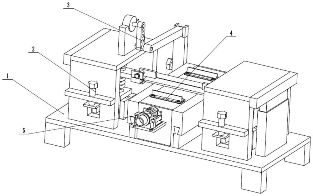
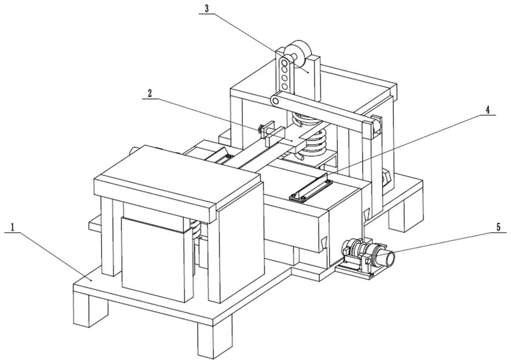
[0032] Such as Figure 1 to Figure 12As shown, the metal surface treatment liquid production device includes a production frame 1, an adjustment dispenser 2, a motion adder 3, a flow mixing box 4 and two quantitative discharge pipes 5, and the adjustment dispenser 2 is fixedly connected to the production machine On the frame 1, the motion adder 3 is fixedly connected to the upper end of the production frame 1, and the motion adder 3 is fixedly connected to the flow mixing box 4 through bolts, and the flow mixing box 4 is slidingly connected to the production frame 1. Two quantitative discharge pipes 5 are respectively fixedly connected and communicated with the front and rear ends of the flow mixing box 4, and the upper end of the flow mixing box 4 is fitted with the adjustment dispenser 2. Control the reciprocating distance of the flow mixing box 4 on the production frame 1 by the motion adder 3, and then control the amount of inflow and discharge of the two quantitative disc...

specific Embodiment approach 2

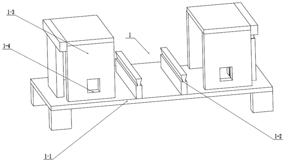
[0034] Such as Figure 1 to Figure 12 As shown, this embodiment will further illustrate Embodiment 1. The production frame 1 includes a fixed base 1-1, two fixed T-shaped sliders 1-2, two fixed frames 1-3 and two limiters. Position sliding groove 1-4, two fixed T-shaped sliders 1-2 are evenly fixedly connected on the fixed base 1-1, and two fixed frames 1-3 are respectively fixedly connected to the two upper ends of the fixed base 1-1. On the side, the rear end of the fixed frame 1-3 is provided with a through limit sliding slot 1-4.

specific Embodiment approach 3

[0036] Such as Figure 1 to Figure 12 As shown, this embodiment will further explain the second embodiment. The adjustable dispenser 2 includes two sets of longitudinally fixed sliding seats 2-1, two adjustable sliding frames 2-2, and two limit sliding tables 2- 3. Two adjusting bolts 2-4, two fixed threaded seats 2-5, two spring shafts 2-6, two buffer top plates 2-7, two lower springs 2-8 and two upper springs 2-9 Two groups of longitudinally fixed sliding seats 2-1 are respectively fixedly connected to the lower ends of the inner walls of the two fixed frames 1-3, and the adjustable sliding frame 2-2 is connected to the vertically fixed sliding seats 2-1 through the sliding block longitudinally, and the limit The sliding table 2-3 is fixedly connected to the adjustable sliding frame 2-2 and is slidably connected in the limiting sliding groove 1-4, and the lower end of the adjusting bolt 2-4 is rotatably connected in the limiting sliding table 2-3 and passed through The thre...


PUM


Abstract

The invention relates to the field of metal surface treatment liquid, in particular to a production device of a metal surface treatment liquid. The device comprises a production rack, an adjusting dispenser, a motion adder, a flow mixing box and two quantitative discharge pipes, the adjusting dispenser is fixedly connected to the production rack, the motion adder is fixedly connected to the upper end of the production rack, the motion adder is fixedly connected with the flow mixing box through bolts, the flow mixing box is connected to the production rack in a front-back sliding mode, the two quantitative discharge pipes are fixedly connected and communicated to the front end and the rear end of the flow mixing box respectively, and the upper end of the flow mixing box is attached to the adjusting dispenser. The device has the beneficial effects that: in the process of producing the metal treatment liquid, the liquid contacts with and is mixed with dangerous materials for reaction in an adjustable intermittent manner, and the danger is reduced while effective reaction is achieved.

Description

technical field [0001] The invention relates to the field of metal surface treatment liquid, more specifically to a metal surface treatment liquid production device. Background technique [0002] Patent No. CN201120409067.2 discloses a production device for metal surface treatment liquid, which includes a water storage tank, a high-level tank and a reaction kettle, and is characterized in that the water storage tank is connected to the high-level tank through a pipeline, and the high-level tank is connected to the high-level tank through a pipeline. Reactor connection. The metal surface treatment liquid production device obtained by the utility model has simple structure and convenient operation, and the produced metal surface treatment liquid is evenly mixed. However, this equipment cannot stably and intermittently add dangerous raw materials. Contents of the invention [0003] The purpose of the present invention is to provide metal surface treatment liquid production ...

Claims


Application Information

Patent Timeline
Patent Type & Authority Applications(China)
IPC IPC(8): B01F11/00B01F15/00B01F15/02
CPCB01F31/00B01F31/70B01F35/325B01F35/3204B01F35/43B01F35/714B01F35/754
Inventor 郑玉莲
Owner 郑玉莲
Why Eureka
Try Eureka