A liquid phase hydrogenation reactor and hydrogenation process

A liquid-phase hydrogenation and hydrogenation reaction technology, which is applied in the fields of hydrogenation treatment process, sustainable manufacturing/processing, petroleum industry, etc., can solve problems such as side reactions and cracking reactions, severe reaction heat release, and fast reaction rate

Active Publication Date: 2022-07-12
CHINA PETROLEUM & CHEM CORP +1
View PDF13 Cites 0 Cited by
  • Summary
  • Abstract
  • Description
  • Claims
  • Application Information

AI Technical Summary

Problems solved by technology

However, the following problems still exist in the conventional downflow liquid-phase hydrogenation reactor and reaction process: (1) The concentration of reactants in the fresh material in the early stage of the reaction is high, the hydrogen content is high, the driving force of the reaction process is large, and the initial activity of the catalyst is also high , and the contact between the material and the catalyst in the liquid-phase hydrogenation process is relatively sufficient, so there are problems such as severe reaction heat release, large temperature rise, and difficult control of the process; (2) In the later stage of the reaction, due to the high reaction temperature, if it is still The hydrogenation reaction occurs on the active catalyst, causing the problems of fast reaction rate, side reaction and cracking reaction. Therefore, a catalyst with appropriate activity should be used in the later stage of the reaction to control the reaction rate and improve the reaction yield. (3) Since the late stage of the reaction is still a liquid-phase hydrogenation reaction process, the gas products generated by the reaction are still dissolved in the liquid material, that is, the conventional reaction is adopted in the liquid-phase hydrogenation reaction process It is difficult to separate by the stripping method of the reactor, which requires a large stripping surface area. If the reaction gas is not stripped out in time and removed, the reaction conversion rate in the later stage of the reaction will be reduced, so that the ideal hydrogenation cannot be achieved. Reaction depth; (4) During the reaction process, with the flow of materials in the hydrogenation reactor and the consumption of hydrogen, the dissolved and dispersed state of hydrogen in the oil has gradually changed, resulting in the hydrogen bubbles dissolved around the oil molecules. When the reaction occurs, the bubbles that have not reacted gradually coalesce into large bubbles, so that the oil cannot continuously provide hydrogen during the hydrogenation reaction, and it will also increase the side reaction or cracking reaction
[0008] In summary, most of the liquid-phase hydrogenation reactors in the prior art are based on the method of dissolving hydrogen or hydrogen dissolving components, and the method of supplementing hydrogen to improve the reaction efficiency. The external stripping facilities will flash the hydrogen sulfide and ammonia generated by the reaction. These methods do not solve the problem of severe exothermic reaction, uneven temperature rise, low reaction conversion rate in the later stage, and when the required conversion rate is reached during the liquid phase hydrogenation reaction. Therefore, it is necessary to further develop new liquid-phase hydrogenation reactors and liquid-phase hydrogenation reaction processes.

Method used


Image

  • A liquid phase hydrogenation reactor and hydrogenation process
  • A liquid phase hydrogenation reactor and hydrogenation process
  • A liquid phase hydrogenation reactor and hydrogenation process

Examples


Embodiment 1

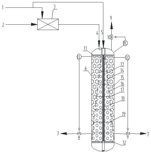
[0049] with attached figure 1 In the described method, the catalyst used in the conical inner cylinder of the liquid-phase hydrogenation reactor is FHDO-18 of Fushun Petrochemical Research Institute, and the catalyst used in the annular cavity is FHDO-10; the liquid-phase hydrogenation reactor feed contains FHDO-18. The amount of hydrogen in the liquid phase hydrogenation reactor is 0.015% of the mass of the feedstock oil, and the hydrogen supplementation amount of the hydrogen diffusion component of the liquid phase hydrogenation reactor is 0.112% of the mass of the feedstock oil; the reaction conditions of the conical inner cylinder of the liquid phase hydrogenation reactor are as follows: the reaction The temperature is 121.2~124.7℃, the reaction pressure is 1.8MPaG, and the liquid hourly volume space velocity is 15.0h -1 ; The reaction conditions of the annular cavity are as follows: the reaction temperature is 124.7~128.1℃, the reaction pressure is 1.75MPaG, and the liqui...

Embodiment 2

[0053] with attached figure 1 In the described method, the catalyst used in the conical inner cylinder of the liquid-phase hydrogenation reactor is FHDO-10 of Fushun Petrochemical Research Institute, and the catalyst used in the annular cavity is FHDO-6; the liquid-phase hydrogenation reactor feed contains FHDO-6. The amount of hydrogen supplied is 0.012% of the mass of the feedstock oil, and the hydrogen supplementation of the hydrogen diffusion component of the liquid-phase hydrogenation reactor is 0.117% of the mass of the feedstock oil. The reaction conditions of the conical inner cylinder of the liquid-phase hydrogenation reactor are as follows: the reaction temperature is 122.4~125.8℃, the reaction pressure is 1.8MPaG, and the liquid hourly volume space velocity is 12.0h -1 ; The reaction conditions of the annular cavity are as follows: the reaction temperature is 125.8-129.2°C, the reaction pressure is 1.75MPaG, and the liquid hourly volume space velocity is 8.8h -1 . ...

Embodiment 3

[0057] with attached figure 1 In the method, the catalyst used in the conical inner cylinder of the liquid-phase hydrogenation reactor is FHDO-18 from Fushun Petrochemical Research Institute, and the catalyst used in the annular cavity is FHDO-6; the liquid-phase hydrogenation reactor feed contains FHDO-6. The amount of hydrogen in the liquid phase hydrogenation reactor is 0.025% of the mass of the feedstock oil, and the hydrogen supplementation of the hydrogen diffusion component of the liquid-phase hydrogenation reactor is 0.104% of the mass of the feedstock oil. The reaction conditions of the conical inner cylinder of the liquid-phase hydrogenation reactor are as follows: the reaction temperature is 120.7~124.2℃, the reaction pressure is 1.8MPaG, and the liquid hourly volume space velocity is 12.0h -1 ; The reaction conditions of the annular cavity are as follows: the reaction temperature is 124.2~127.5℃, the reaction pressure is 1.75MPaG, and the liquid hourly volume space...


PUM

PropertyMeasurementUnit
sizeaaaaaaaaaa
pore sizeaaaaaaaaaa
porosityaaaaaaaaaa

Abstract

The invention discloses a liquid-phase hydrogenation reactor and a hydrogenation process, comprising an inner cylinder and a reactor shell, the inner cylinder is conical, the top and bottom of the inner cylinder are open, the bottom edge is tightly connected with the inner wall of the reactor, and the inner cylinder is open. A number of small holes are opened on the cylinder wall; a ceramic membrane tube bundle is vertically arranged on the axial direction of the reactor, and the ceramic membrane tube bundle communicates with external hydrogen; the inner cylinder is filled with hydrogenation catalyst I, the annular cavity is filled with hydrogenation catalyst II, and hydrogenation catalyst I The activity of the catalyst is higher than that of the hydrogenation catalyst II; the inlet of the raw material of the reactor is connected to the top of the inner cylinder; the flow mode of the material in the inner cylinder is from top to bottom; the flow mode of the material in the annular cavity is from top to bottom. The invention can effectively control the contact time between the material and the catalyst in the whole process of the hydrogenation reaction, make the temperature rise of the catalyst bed more uniform, solve the problems of severe exotherm and inhibit the reaction conversion rate in the reaction process, and realize the whole liquid phase hydrogenation reaction process Both achieve higher hydrogenation reaction rate and conversion.

Description

technical field [0001] The invention belongs to the fields of chemical industry and petrochemical industry, in particular to a liquid-phase hydrogenation reactor and a hydrogenation process. Background technique [0002] Liquid-phase hydrogenation technology is a new type of hydrogenation technology. Hydrogen is dissolved in feedstock oil in advance, and the hydrogen required for hydrogenation is met by a large number of liquid-phase circulations, which overcomes the hydrogen diffusion in conventional trickle bed hydrogenation. Due to the influence of mass transfer, the hydrogenation reaction is carried out in the kinetic control zone. Therefore, compared with the traditional fixed-bed gas / liquid / solid three-phase hydrogenation process, the liquid-phase hydrogenation process has the advantages of fast hydrogenation reaction rate, high reaction High efficiency, low energy consumption, low investment and many other advantages have been widely recognized and applied. [0003] ...

Claims


Application Information

Patent Timeline
Patent Type & Authority Patents(China)
IPC IPC(8): B01J8/04C10G67/00
CPCB01J8/04B01J8/0492B01J8/0496C10G67/00B01J2208/025C10G2300/4006C10G2300/4012C10G2300/4018Y02P20/52
Inventor 高峰杨秀娜阮宗琳何佳杨振宇
Owner CHINA PETROLEUM & CHEM CORP
Why Eureka
Try Eureka