
Sorting machine for processing electronic components

A technology for electronic components and sorting machines, applied in sorting and other directions, can solve problems such as inspection accuracy errors, photographing area restrictions, and different lighting environments, and achieve the effects of reducing production costs, improving processing speed, and improving accuracy.

Pending Publication Date: 2021-04-13
TECHWING CO LTD
View PDF10 Cites 1 Cited by
  • Summary
  • Abstract
  • Description
  • Claims
  • Application Information

AI Technical Summary

Problems solved by technology

[0014] First, suppliers who produce and provide sorting machines cannot deliver goods to consumers who use the sorting machines in a state that can determine whether loading is defective
The reason for this is that even if the same part is captured by the camera, different images may be captured due to various lighting environments or the color of electronic components, so different reference images may be obtained depending on the situation.
However, because the lighting environment in which the sorter is used by each customer is different, the job of acquiring a reference image or setting a specific area to be compared must be done as part of the process of setting up the sorter at the customer's workplace
In addition, the lighting environment of the workplace may change at any time, so it is necessary to repeat the troublesome work of acquiring reference images
[0015] Second, because consumers arbitrarily decide a specific area of ​​the reference image, the results vary from person to person, so even if the second prior art is applied, errors that are almost the same as those of the first prior art will continue to occur in terms of inspection accuracy
Also, errors may occur depending on who (which manager) designates a specific area, so the reliability of the inspection cannot be guaranteed uniformly
[0016] In addition, in order to obtain accurate reference images, the camera must be high-performance and expensive, and the operator must have high proficiency, not only that, but there are also various constraints such as the need to always approach with the same judgment
[0017] Also, in the case where a reference image is to be stored, the image data capacity is large, and the shooting area for acquiring the reference image is limited, so it is necessary to set up a shooting device and there is a limitation in this setting, and it is necessary to secure a space where the camera can focus each time, Therefore, the size of the sorting machine is increased

Method used


Image

  • Sorting machine for processing electronic components
  • Sorting machine for processing electronic components
  • Sorting machine for processing electronic components

Examples


Embodiment Construction

[0058] Referring to the accompanying drawings, preferred embodiments according to the present invention will be described, and for the sake of conciseness of description, descriptions on repeated or substantially identical configurations will be omitted or compressed as much as possible.

[0059]

[0060] For the tray T, for example, the technology of Korean Laid-Open Patent No. 10-2008-00406541 can be referred to.

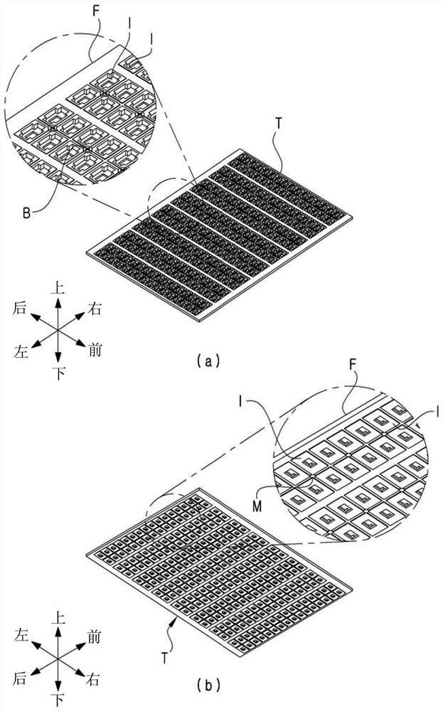
[0061] figure 1 (a) and (b) are a schematic plan perspective view and bottom perspective view about the tray T.

[0062] Tray T is equipped with frame F and insert I.

[0063] The frame F constitutes the skeleton of the tray T, and the inserts I are arranged on the frame F in a row of 16×16.

[0064] As is well known, the interposer 1 has a housing space for housing electronic components, and has a latch for securing the electronic components housed in the housing space.

[0065] and, figure 1 The tray T has the following structure: four inserts I in a 2×2 ...


PUM


Abstract

The invention relates to a sorting machine for processing electronic components. The main feature of the present invention is that, after storing a reference information value (numerical value or form) on an electronic component, the lower surface of a tray on which the electronic component is loaded is photographed, and a comparison information value is acquired from the obtained image, and then the reference information value and the comparison information value are compared. According to the present invention, since the loading failure is determined substantially by comparison of the numerical information, it is possible to ensure the reliability of the determination of the loading failure.

Description

technical field [0001] The present invention relates to a sorter for processing electronic components, in particular to a technique for judging loading miss of electronic components. Background technique [0002] The produced electronic components are shipped through various processing processes (testing process or sorting process, etc.). [0003] Dedicated sorting machines for handling electronic components are used in various processes for electronic components. [0004] Sorters can be manufactured in various forms depending on the process in which they are used. Among various types of sorting machines, many types of sorting machines use trays as a medium for conveying electronic components. One of the reasons for using trays is to increase processing capacity by processing large numbers of electronic components together. [0005] However, in order to perform processing operations (testing / sorting, etc.) on electronic components loaded on a pallet, the electronic compon...

Claims


Application Information

Patent Timeline
Patent Type & Authority Applications(China)
IPC IPC(8): B07C5/36B07C5/34B07C5/02
CPCB07C5/361B07C5/34B07C5/02
Inventor 黄义准赵德显秦昇佑
Owner TECHWING CO LTD
Learn More