
Self-supporting pneumatic hammer positioner with universal joint

a pneumatic hammer and universal joint technology, applied in the direction of drilling machines and methods, portable percussive tools, anchoring bolts, etc., can solve the problems of requiring human eye-hand coordination, releasing debris from the top vault of the mining tunnel, and affecting the safety of workers, so as to improve the acceptance level of invention, reduce physical damage, and promote learning

Active Publication Date: 2020-02-11
R N P IND
View PDF39 Cites 1 Cited by
  • Summary
  • Abstract
  • Description
  • Claims
  • Application Information

AI Technical Summary

Benefits of technology

The solution significantly reduces physical effort and exposure to vibrations, minimizing the risk of musculoskeletal and vibration-related disorders, while maintaining the precision and control of traditional manual operations, thereby enhancing safety and productivity.

Problems solved by technology

Workers in the mining industry are subject to significant physical constraints.
Indeed, some mining operations require that workers handle heavy tools that generate intense vibrations to accomplish their tasks manually.
Indeed the nature of the soil as well as normal drilling and blasting cause the release of debris from the top vault of the mining tunnel.
This still remains a delicate operation requiring human eye-hand coordination.
However, these tools are very heavy and generate higher vibration levels.
Along with other equipment, the jack leg is a tool weighing approximately 57 kilograms and which generates high levels of vibration.
Thus, these mine workers sustain significant physical exertion during work and are exposed to very significant vibrations while working in a hazardous and often hostile environment.
Therefore they are exposed to a high risk of injury as well as risk to develop certain occupational borne diseases associated, among others, to exposure to body vibrations.
So the scientific community recognizes that prolonged exposure to high levels of vibration may have adverse effects on health, and more specifically: repetitive hand movements may be a factor of ischemia; unnatural hand positions (maladaptive grip, variable work posture and height) cause additional constraints and workloads which can lead to hardening of muscles and ligaments, which can cause injuries; tight grip (used with one hand, with vibrations, that we do not want to release) causes vascular and sensorimotor disorders; mechanical stress exerted on the palms of the hands (against handling blows, strike movements on components, working with a steel tool); vibrations; and Raynaud's syndrome (ischemia in the fingers, finger vasoconstriction induced by the nervous system).
These factors are most incapacitating for workers with possible permanent physical damage.
These factors in addition to increasing the specific health hazard of mine workers also have longer-term consequences.

Method used


Image

  • Self-supporting pneumatic hammer positioner with universal joint
  • Self-supporting pneumatic hammer positioner with universal joint
  • Self-supporting pneumatic hammer positioner with universal joint

Examples


first embodiment

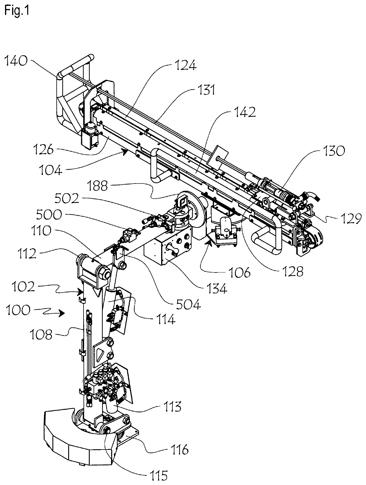
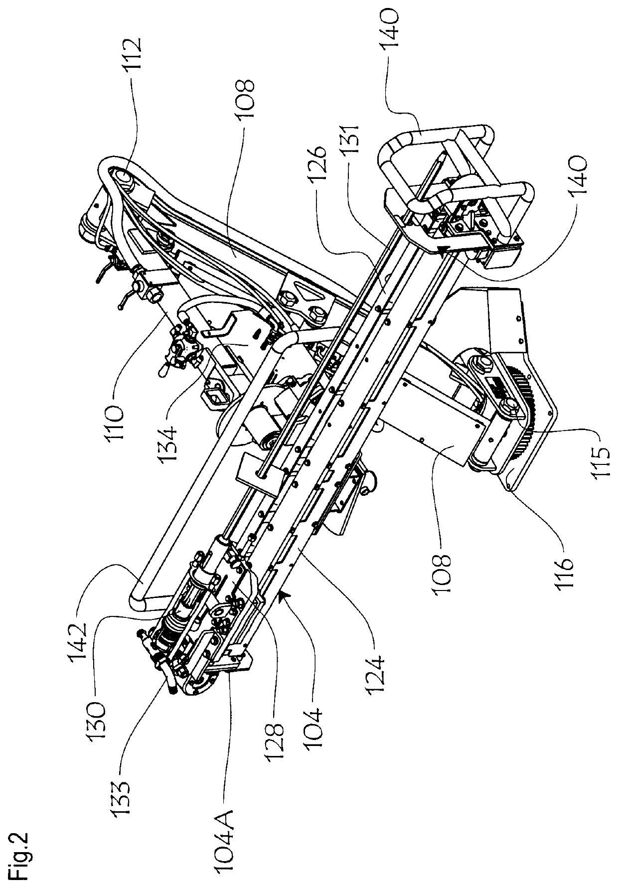
[0057]Drill positioner 100 shown in FIGS. 1 to 28 consists of an articulated mast or boom 102, turret 104 and a two axes joint assembly 106 interconnecting an intermediate section of the turret with the outer end of the boom. Boom 102 includes lower and upper arms 108, 110, interconnected by a horizontal pivot mount 112. Hydraulic ram 114 pivotally biases boom upper arm 110 relative to boom lower arm 108 about pivot 112. A coupling assembly 116 is mounted to the bottom end of lower arm 108. Another hydraulic ram 113 pivots boom lower arm 108 relative to coupling 116 about pivot 115.

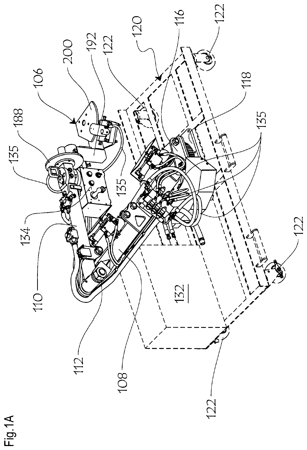
[0058]In one embodiment, illustrated in FIG. 1A, coupling assembly 116 releasably rotatably interlocks with a complementary rotatable coupling mount 118 over a platform 120 movably carried over ground by two pairs of corner casters 122. Couplings 116, 118, enable rotation of the boom lower arm 108 about a vertical axis. To the outer end of boom upper arm 110, opposite boom coupling 116 is releasably fixed...

second embodiment

[0104]In turret of FIGS. 29 to 36, the pivotal inner end portions of drill bit centering arms 1146A, 1148A, are pivotally interconnected by an S-shape interlink rod 1154, at pivot mounts 1154A, 1154B being parallel to but slightly offset relative to pivot mounts 1146A, 1148A, in such a fashion that scissor type movement of arms 1146, 1148 is achieved, i.e. when arm 1146 moves away from arm 1148, arm 1148 will concurrently pivotally move away due to the offset interlink rod 1154. A manual lever 1156 projecting transversely outwardly from the main body 1105 of turret 1104 is operatively connected at pivot axle 1146A, all in such a way that in a raised condition of lever 1156, the top ends of arms 1146A, 1148A, are closed against one another (FIGS. 29, 29A, 29B, 29C), and cylindrical channel 1150, 1152 is formed (FIG. 29C), whereas when lever 1156 is manually brought down to a lowered condition (FIGS. 30, 30A), the top ends of arms 1146B, 1148B, are spread apart. In an alternate embodi...


PUM


Abstract

A manually operated pneumatic rock drill positioner for mining shaft wall boring, said positioner comprising: an articulated boom having one end for releasable coupling to a mobile ground platform and another end opposite said one end thereof; a rigid elongated drill turret defining a main body with an exposed outer wall, an inner wall opposite said outer wall, and first side edge wall and second side edge wall opposite said first side edge wall, and first end and second end opposite said first end, a lengthwise rail member integrally mounted to said turret outer wall; a carriage slidingly engaging said rail member, said carriage for slidingly carrying a pneumatic drill head over said turret exposed outer wall for reciprocating motion thereof between said first end and second end thereof; drive means for power actuating said carriage sliding motion along said rail member; a cradle member releasably anchored to said boom another end and defining a well sized and shaped for releasable engagement by an intermediate section of said turret inner wall and said first side edge wall thereof; anchoring means for anchoring said turret to said cradle member; first coupling means for pivotally connecting said turret to said cradle member for relative pivotal movement of said turret about said cradle member along a first axis; second coupling means for pivotally connecting said turret to said cradle member for relative tilting movement of said turret about said cradle member along a second axis transverse to said first axis; all in such a way that the intersection of said first axis and second axis coincides with the center of gravity of said turret positioner and is located within said turret main body, providing a balanced load-free manual operation of the positioner.

Description

CROSS REFERENCE DATA[0001]This patent application is a national phase application under 35 U.S.C. 371 of international patent application PCT / CA2015 / 000464 filed Aug. 17, 2015, which claims Paris convention priority based upon U.S. patent application No. 62 / 038,463 filed 18 Aug. 2014, each of which is hereby incorporated by reference in its entirety.BACKGROUND OF THE INVENTION[0002]It is well known that the mining sector is one of hard work. Workers in the mining industry are subject to significant physical constraints. Indeed, some mining operations require that workers handle heavy tools that generate intense vibrations to accomplish their tasks manually.[0003]For example, securing mining shaft ceilings or “vaults” requires the installation of anchors in the rock wall to support a wire mesh to prevent collapsing pieces of fractured rock falling on to workers. Indeed the nature of the soil as well as normal drilling and blasting cause the release of debris from the top vault of the...

Claims


Application Information

Patent Timeline
Patent Type & Authority Patents(United States)
IPC IPC(8): E21B7/02E21B1/02E21D20/00B25D17/28E21B19/086
CPCE21D20/003E21B19/086E21B7/025E21B1/02E21D20/00E21B7/027B25D17/28E21B1/30
Inventor MORISSETTE, DANNYSMITH, ERICKGUIMOND, LUCBLANCHET, GHISLAINJULIEN, GUILLAUMETREMBLAY, GUYLALONDE, RÉJEANMAGNY, JEAN-PIERRELAROCHE, ANTHONYCHROUROU, YOUSSEFJULIEN, ALAINLALIBERTE, STEVEPAQUIN, RAPHAELSIMARD, MAXIMETRUDEL, CLAUDEMENARD, MARTINMANSEAU, TOMMY
Owner R N P IND
Learn More