Purge nozzle module for load port

a technology of purge nozzle and load port, which is applied in the direction of basic electric elements, semiconductor/solid-state device manufacturing, electrical equipment, etc., can solve the problems of port not being secured, port periphery or the tip of the purge nozzle being worn, and the wafer inside being damaged, etc., to achieve the effect of reducing the time and cost required for assembly and replacement, improving air tightness, and reducing manufacturing costs

Active Publication Date: 2020-10-08
AE CO LTD
View PDF0 Cites 1 Cited by
  • Summary
  • Abstract
  • Description
  • Claims
  • Application Information

AI Technical Summary

Benefits of technology

[0036]According to a purge nozzle module for a load port of the present invention, manufacturing cost is reduced because it does not require an actuator, such as a conventional solenoid, and time and cost required for assembly and replacement can be reduced because a pre-assembled module is mounted on a stage.
[0037]In addition, according to the purge nozzle module for the load port of the present invention, since a tip of the purge nozzle is in close contact with a periphery of the port of the FOUP by vacuum pressure, airtightness is improved, and it is possible to maintain a stable connection state.
[0038]In addition, according to the purge nozzle module for the load port of the present invention, compared with a conventional lifting method of a cylinder such as a solenoid, shock, abrasion or damage applied to the FOUP is prevented, so that possibility of failure is low and durability is improved.

Problems solved by technology

Therefore, when the internal space of the FOUP in which the wafer stored has lower in cleanliness than the internal space of the semiconductor manufacturing apparatus, gas inside the FOUP may enter the semiconductor manufacturing apparatus and may adversely affect the gas atmosphere inside the semiconductor manufacturing apparatus.
If the type or shape of the port is different depending on a type of FOUP, there is a problem that a good connection state for securing high airtightness between the purge nozzle and the port cannot be secured.
In addition, if the purge nozzle is raised in the state that the FOUP is not seated in a correct position on the stage, a tip of the purge nozzle is in contact with a periphery of the port at the bottom of the FOUP, and there is also a risk that the periphery of the port or the tip of the purge nozzle may be worn or the wafer inside may be damaged as the FOUP is tilted to one side.

Method used


Image

  • Purge nozzle module for load port
  • Purge nozzle module for load port
  • Purge nozzle module for load port

Examples


Embodiment Construction

[0049]Hereinafter, the inventive concept will be explained in detail with reference to the accompanying drawings. In describing the various embodiments of the present invention, the same reference numerals will be used for the elements having the same technical features.

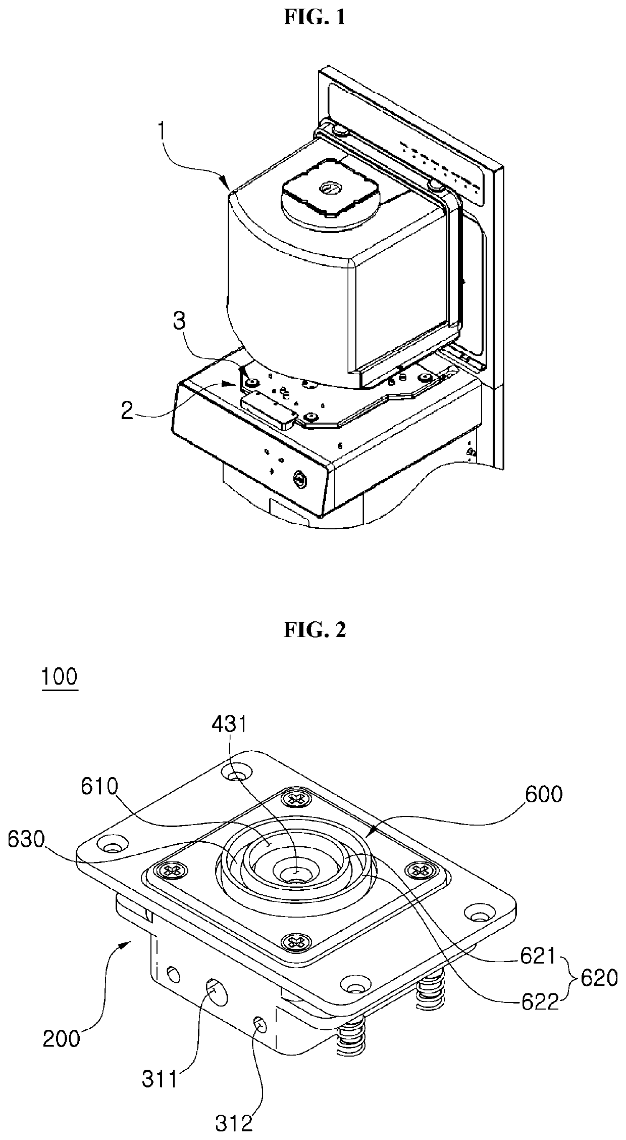
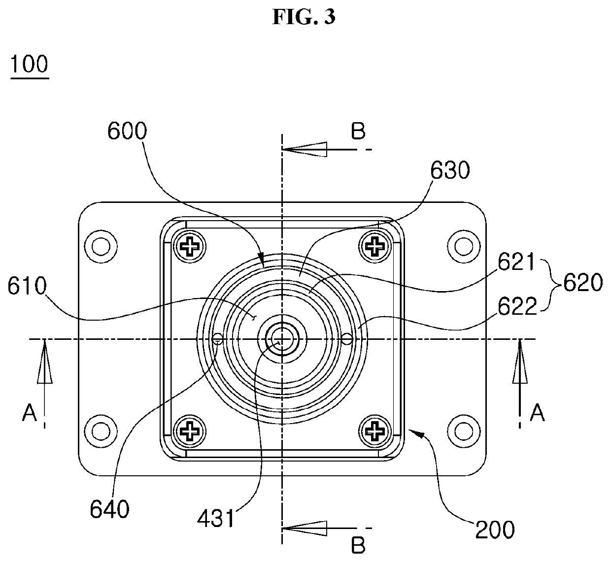
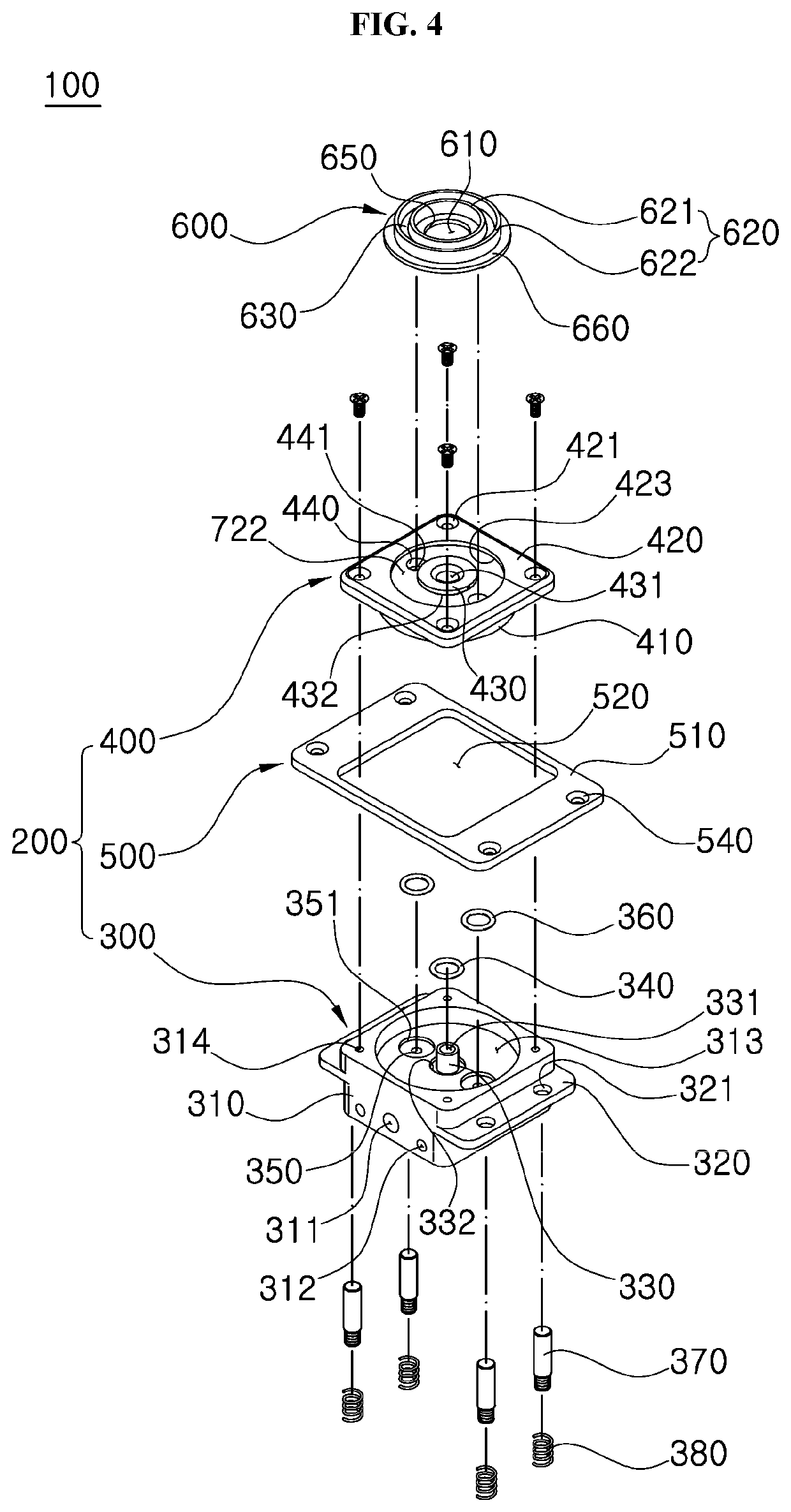
[0050]As described in FIGS. 2 and 3, the purge nozzle module for the load port (hereinafter, ‘fuzzy nozzle module’) 100 according to an embodiment of the present invention includes a nozzle body 200 having a cube block shape, a vacuum pad 600 provided on an upper side of the nozzle body 200.

[0051]A purge hole 431 for supplying purge gas, such as N2, inert gas, or the like is formed in a center of the upper side of the nozzle body 200 the lower side of the nozzle body 200 is injected purge gas from the outside Gas injection hole 311 is formed. A gas injection hole 311 through which purge gas is injected from the outside is formed at a lower side of the nozzle body 200. In addition, at least one exhaust hole 312 is for...


PUM


Abstract

A purge nozzle module for supplying nitrogen (N2) to a semiconductor wafer processing apparatus includes a nozzle body with a purge hole formed at a center thereof, and a vacuum pad combined with an upper side of the nozzle body, having a through hole connected to the purge hole formed therethrough, and making close contact with a bottom of a FOUP (Front Opening Unified Pod) by a vacuum pressure.

Description

CROSS-REFERENCE TO RELATED APPLICATIONS[0001]This application claims priority to Korean Patent Application No. 10-2019-0039078, filed on Apr. 3, 2019, and all the benefits accruing therefrom under 35 U.S.C. § 119, the content of which in its entirety is herein incorporated by reference.BACKGROUND1. Technical Field[0002]Exemplary embodiments of the inventive concept relate to a purge nozzle module. More particularly, exemplary embodiments of the inventive concept relate to a purge nozzle module for providing nitrogen (N2) to a semiconductor wafer processing apparatus.2. Description of the Related Art[0003]A front-opening interface mechanical standard (FIMS) system is a standard proposed by the Semiconductor Equipment and Materials International (SEMI) in a semiconductor manufacturing process.[0004]The FIMS system uses a wafer processing apparatus called a load port for automatically transferring a wafer or a reticle to the FIMS system.[0005]The load port is an interface device that d...

Claims


Application Information

Patent Timeline
Patent Type & Authority Applications(United States)
IPC IPC(8): H01L21/673
CPCH01L21/67389H01L21/67393H01L21/67775H01L21/67017H01L21/67772H01L21/67207
Inventor OH, SHE HYUNKIM, JOUNG YOUN
Owner AE CO LTD
Why Eureka
Try Eureka