
Bicycle labor-saving mechanism

A bicycle and frame technology, applied in the field of bicycle labor-saving mechanisms, can solve problems such as poor stability of the bicycle labor-saving structure, and achieve the effects of compact structure, good working stability and convenient processing.

Pending Publication Date: 2021-04-13
张新金
View PDF1 Cites 0 Cited by
  • Summary
  • Abstract
  • Description
  • Claims
  • Application Information

AI Technical Summary

Problems solved by technology

[0006] The purpose of the present invention is to solve the problem of poor stability of the existing bicycle labor-saving structure in view of the above-mentioned problems existing in the prior art, and to propose a bicycle labor-saving mechanism

Method used


Image

  • Bicycle labor-saving mechanism
  • Bicycle labor-saving mechanism
  • Bicycle labor-saving mechanism

Examples


Embodiment 1

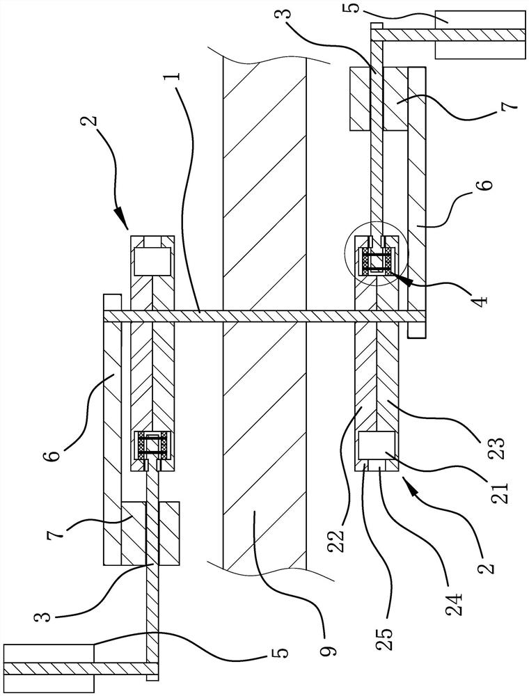
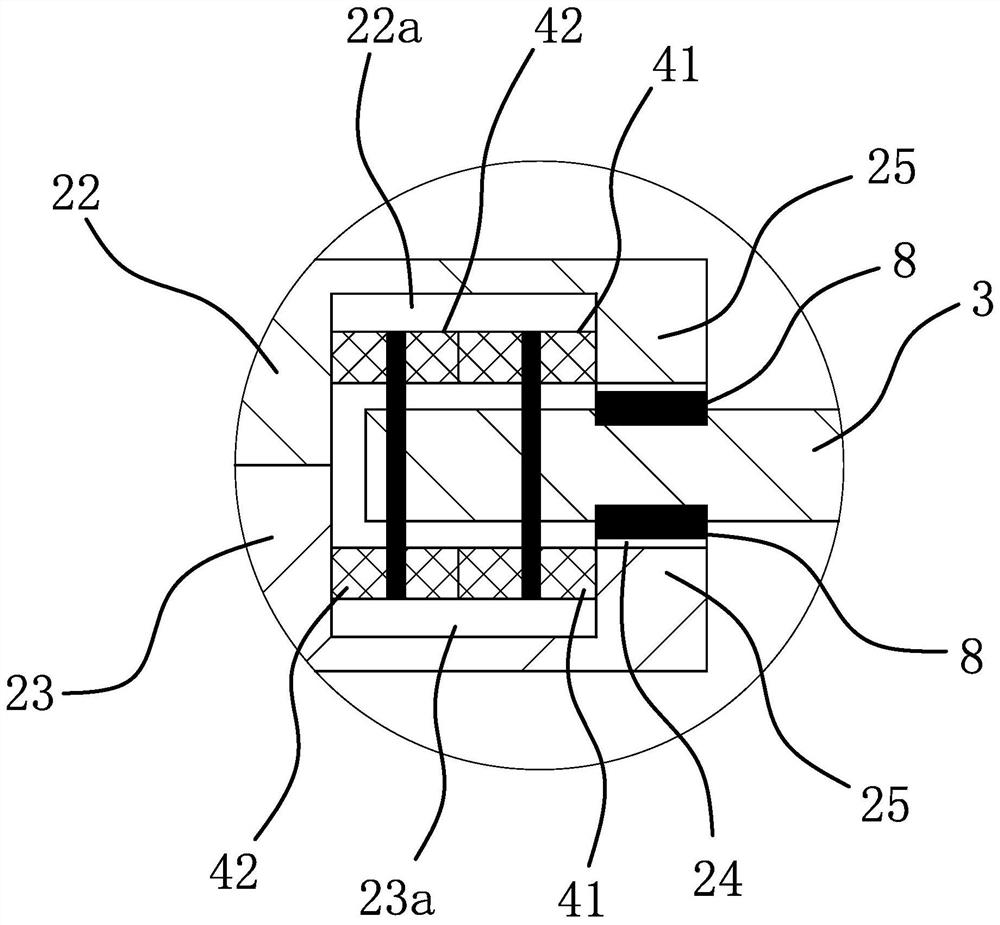
[0035] Such as figure 1 with Figure 7 As shown, the bicycle labor-saving mechanism is connected to the vehicle frame 9, including the central axis 1 horizontally pierced on the vehicle frame 9, and two guide rails with annular guide grooves 21 respectively sleeved on the outer sides of the two ends of the central axis 1. 2 and two pedal rods 3 in the shape of square rods, the two pedal rods 3 are arranged perpendicular to the central axis 1, and the inner ends of the pedal rods 3 are connected with guides 4 that snap into the corresponding guide grooves 21, Foot pedals 5 are connected to the outer ends of the pedal rods 3 , and the distance between the pedals 5 and the central axis 1 increases or decreases gradually when the pedal rods 3 move along the guide groove 21 . In this embodiment, the two guide rails 2 are substantially disc-shaped and fixed on both sides of the vehicle frame 9 in an axisymmetric manner. 21 is roughly in the shape of a duck egg; the positions where...

Embodiment 2

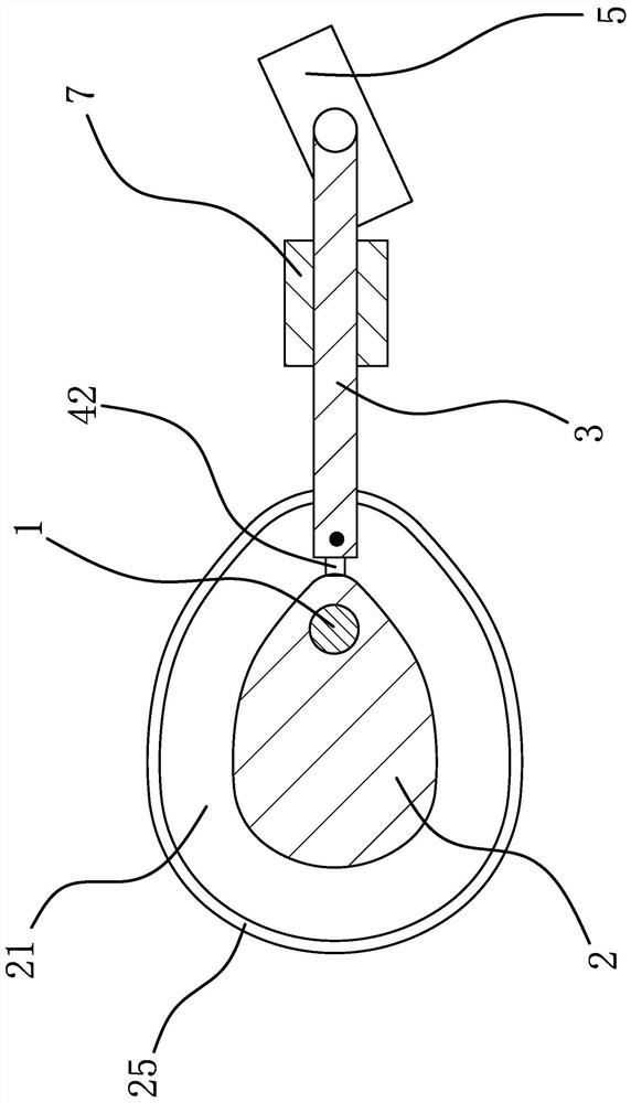
[0044] Such as Figure 5 As shown, the solution of this embodiment is roughly the same as that of Embodiment 1, the difference is that: the number of the rolling element 3 42 is only one and it is rotatably connected to the inner end of the pedal rod 3; the guide groove 21 is round Shape; Pedal bar 3 is round bar shape.

Embodiment 3

[0046] Such as Image 6 As shown, the solution of this embodiment is roughly the same as that of Embodiment 1, except that the number of rolling elements 3 42 is three, two of which are rotatably connected to both sides of the pedal bar 3, and the third It is rotatably connected to the inner end of the pedal rod 3 .


PUM


Abstract

The invention provides a bicycle labor-saving mechanism, belongs to the technical field of bicycles, and solves the problem that an existing bicycle labor-saving structure is low in stability. The bicycle labor-saving mechanism comprises a middle shaft, two guide rails with guide grooves and two pedal rods, the two ends of the middle shaft penetrate through the eccentric positions of the two guide rails respectively, the inner ends of the two pedal rods are connected with guide pieces clamped into the corresponding guide grooves, and the outer ends of the pedal rods are connected with pedals. The labor-saving mechanism further comprises two transmission pieces perpendicular to the middle shaft, the two transmission pieces are arranged at the two ends of the middle shaft respectively and fixedly connected with the middle shaft, each transmission piece is provided with a cylindrical sliding cylinder, the two pedal rods penetrate through the corresponding sliding cylinders respectively, and the sliding cylinders are located between the guide pieces and the outer end portions of the pedal rods. The bicycle labor-saving mechanism has the advantage of being high in stability.

Description

technical field [0001] The invention belongs to the technical field of bicycles and relates to a bicycle labor-saving mechanism. Background technique [0002] With the concept of energy conservation and environmental protection deeply rooted in the hearts of the people and the widespread popularity of public bicycles and shared bicycles, bicycle travel has gradually become an important choice for people to travel. Existing bicycles all adopt chain transmission. After the user steps on the pedal, the pedal rod drives the rotating shaft and the sprocket to rotate circumferentially, and then drives the chain transmission to make the bicycle move forward. However, the length of the pedal rods of existing bicycles is all fixed, and the riding process is relatively laborious. [0003] For this reason, people have designed a kind of telescoping pedal rod labor-saving bicycle, and have applied for Chinese patent, and its application number is: 201710725315.6; Publication number is:...

Claims


Application Information

Patent Timeline
Patent Type & Authority Applications(China)
IPC IPC(8): B62M1/36B62M3/08B62M9/00B62M23/00
CPCB62M1/36B62M3/08B62M9/00B62M23/00
Inventor 张新金
Owner 张新金
Learn More