Cover discharging discharging machine

A technology of unloading machine and cover plate, which is applied in the direction of conveyor objects, transportation and packaging, etc. It can solve the problems that cannot be coordinated, the steps cannot be coordinated at the same time, and there are many manual operations, so as to achieve the effect of convenient material collection

Active Publication Date: 2021-04-13
象平半导体设备(苏州)有限公司
View PDF8 Cites 1 Cited by
  • Summary
  • Abstract
  • Description
  • Claims
  • Application Information

AI Technical Summary

Problems solved by technology

[0002] At present, the blanking machine and the steps to be carried out cannot be carried out simultaneously, and more manual operations are required; in view of the fact that the blanking steps cannot be coordinated, and the blanking machine is not automatic enough, for this reason, we propose a lower cover blanking machine

Method used


Image

  • Cover discharging discharging machine
  • Cover discharging discharging machine

Examples


Embodiment Construction

[0018] In order to make the technical means, creative features, goals and effects achieved by the present invention easy to understand, the present invention will be further described below in conjunction with specific embodiments.

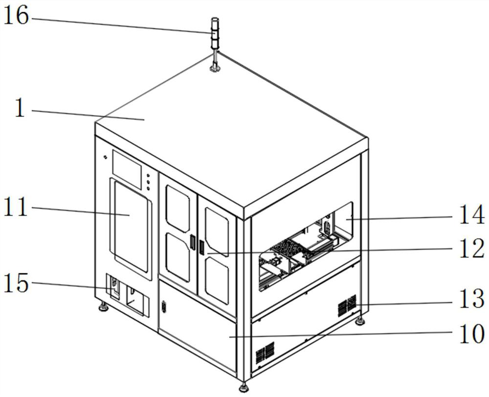
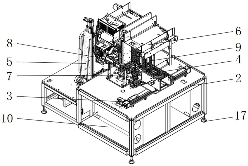
[0019] Such as Figure 1-2 As shown, the lower cover unloading machine includes a device main body 1. A mounting frame 2 is provided on the inner side of the device body 1. A guide rail 3 is provided on the outer surface of the upper end of the mounting frame 2. A plate receiving mechanism 4 is provided on the upper end of the guide rail 3. The mounting frame The outer surface of the upper end of 2 is provided with a material box conveying mechanism 5, and the upper end of the plate receiving mechanism 4 is provided with a cover plate conveying mechanism 6, and one side of the plate receiving mechanism 4 is provided with a cover plate platform 7, and one side of the material box conveying mechanism 5 is provided with There is a feeding channel 8 f...


PUM


Abstract

A cover discharging discharging machine comprises a device body; a mounting frame is arranged on the inner side of the device body; a guide rail is arranged on the outer surface of the upper end of the mounting frame; a plate collecting mechanism is arranged at the upper end of the guide rail; a material box carrying mechanism is arranged on the outer surface of the upper end of the mounting frame; a cover plate carrying mechanism is arranged at the upper end of the plate collecting mechanism; a cover plate collecting platform is arranged on one side of the plate collecting mechanism; a material box conveying flow channel is arranged on one side of the material box carrying mechanism; and a cover plate stock bin is arranged at the lower end of the cover plate carrying mechanism. According to the cover discharging discharging machine, through the cover plate carrying mechanism, the cover plate collecting platform and the material box conveying flow channel, the steps can be compact, manual operation needing to be carried out can be reduced, operation is easy and convenient, and the cover discharging discharging machine is more intelligent and more practical.

Description

technical field [0001] The invention belongs to the technical field of cutting machine equipment, and in particular relates to a lower cover cutting machine. Background technique [0002] At present, the blanking machine and the steps to be carried out cannot be carried out simultaneously, and more manual operations are required; in view of the fact that the blanking step cannot be coordinated, and the blanking machine is not automatic enough, for this reason, we propose a lower cover blanking machine. Contents of the invention [0003] The main purpose of the present invention is to provide a lower cover cutting machine, which can effectively solve the problems in the background technology. [0004] In order to achieve the above object, the technical scheme that the present invention takes is: [0005] The lower cover unloading machine includes a device main body. A mounting frame is provided on the inside of the device body. A guide rail is provided on the outer surface...

Claims


Application Information

Patent Timeline
Patent Type & Authority Applications(China)
IPC IPC(8): B65G47/82B65G47/52
CPCB65G47/82B65G47/52
Inventor 万昌海
Owner 象平半导体设备(苏州)有限公司
Why Eureka
Try Eureka