
Film feeding device of sheet ironing machine

A film feeding device and film feeding technology are applied in the decoration, transportation and packaging of textiles, textiles and papermaking, etc., and can solve the problems of not improving the tension of the film belt, increasing the tension of the film belt, and slipping the film belt. and other problems, to achieve the effect of improving the guiding and conveying efficiency, avoiding pulling deformation, and reducing the traction force

Pending Publication Date: 2021-04-13
浙江镨美科智能刺绣设备有限公司
View PDF1 Cites 0 Cited by
  • Summary
  • Abstract
  • Description
  • Claims
  • Application Information

AI Technical Summary

Problems solved by technology

[0004] There is a defect in this prior art: the film tape (material tape) pulled by the guide mechanism (feeding roller assembly) of the ironing machine is ejected by the rotation of the film tape reel (material tape reel), and the film tape reel is in the process of rotation It has damping. If the damping is too high, the tension of the film tape from the film tape reel to the stamping seat will gradually increase until it is completely tightened, so that the guiding mechanism will slip when pulling the film tape, causing the film tape to be pulled. The traction distance is too short, causing the part of the film tape to be punched out of the through hole to be within the punching range, and then there will be gaps in the punched film, which affects the quality of the stamping sheet, and the tape guide in the prior art Wheels and feeding belt guide rollers only play the role of guiding the film belt, and have no effect on improving the tension of the film belt

Method used


Image

  • Film feeding device of sheet ironing machine
  • Film feeding device of sheet ironing machine
  • Film feeding device of sheet ironing machine

Examples


Embodiment example 1

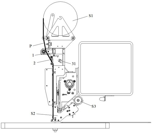
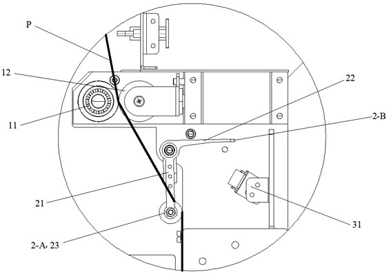
[0036] refer to figure 1 , figure 2 , a film feeding device of a hot sheet machine, which is arranged between the film tape reel S1 of the hot sheet machine and the stamping seat S2, which includes an active film feeding mechanism 1, a swing structure 2, and an induction system. The active film feeding mechanism 1 includes a film feeding mechanism located at The driving roller 11, the driven roller 12, and the drive motor for driving the driving roller 11 under the film tape reel S1, wherein the driving roller 11 and the driven roller 12 are respectively located on both sides of the film belt P, and the two are attached to the film On both sides of the tape P, start the driving motor to drive the driving roller 11 to rotate, drive the driven roller 12 to pull the film tape P, and pull and transport the film tape P on the film tape reel S1 to the stamping seat S2.

[0037] The swing structure 2 is located below the active film feeding mechanism 1 and can rotate on a fixed axi...

Embodiment example 2

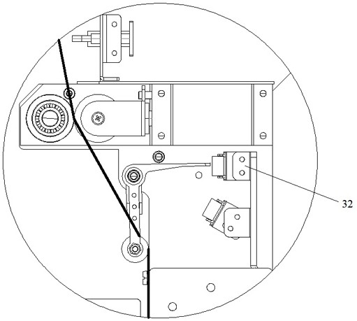
[0046] refer to image 3 and combine figure 1 , on the basis of implementing Case 1, the sensing system also includes a second sensor 32. After the active film feeding mechanism 1 is started, when the tension of the film belt P pulled and output by the active film feeding mechanism 1 reaches the minimum threshold, the second sensor 32 senses the second contact end 2-B and sends a stop signal to the active film feeding mechanism 1. The minimum threshold of the tension of the film belt P is also set according to the actual application situation. Usually, the first swing arm 21 and the second swing arm 22. The tension of the corresponding membrane tape P is set as the lowest threshold when it falls naturally.

[0047] Compared with the implementation case 1, if the active film feeding mechanism 1 allows slippage, the control of the tension of the film belt P in the implementation case 2 is more precise.

Embodiment example 3

[0049] refer to Figure 4 , Figure 5 , Image 6 and combine figure 1 , is different from implementation case 1 and implementation case 2. There are multiple driven rollers 12 and swing structures 2, and the frame S4 ​​of the ironing machine is installed side by side with multiple driven rollers 12 and multiple swing structures along its translation direction. 2. To correspond to a plurality of film tapes P, the casing S5 or the main beam S6 of the ironing machine is equipped with an induction system, which is used to sense the second contact end of the swing structure 2 corresponding to the film tape P currently being punched. A plurality of said induction systems are installed side by side along the translation direction of the frame S4 ​​of the ironing machine to correspond to a plurality of swing structures 2 .

[0050] Each driven roller 12 is equipped with a supporting mechanism 4, and the supporting mechanism 4 includes a supporting rod 41, a mounting frame 42, and a...


PUM


Abstract

The invention discloses a film feeding device of a sheet ironing machine. The device is located between a film belt disc and a stamping seat of the sheet ironing machine, and comprises an active film feeding mechanism, a swing structure and an induction system, the swing structure is provided with a first contact end and a second contact end, and a film belt output by the active film feeding mechanism can drive the first contact end and enable the swing structure to rotate. The induction system comprises a first sensor, and when the tension degree of the film belt output by the active film feeding mechanism reaches the maximum threshold value, the first sensor senses the second contact end and sends a starting signal to the active film feeding mechanism to enable the active film feeding mechanism to convey the film belt. The device has the beneficial effects that the film belt between the film belt disc and the stamping seat can be loosened, and the phenomenon that a guide mechanism of the sheet ironing machine slips is avoided.

Description

technical field [0001] The invention relates to a film feeding device, in particular to a film feeding device of a sheet ironing machine. Background technique [0002] At present, all kinds of embroidery are decorated with bright films or sequins to achieve an aesthetic effect. There are many types and colors of decorative bright films. Usually, a stamping machine (also known as a layout machine or a placement machine) is used to cut off the film tape by punching. Form a film and stick it on the surface of the embroidery. [0003] Prior Art Publication No. CN111910353A discloses a modular combination ironing machine head and punching needle buffer mechanism cooperation structure and ironing machine. Referring to the accompanying drawings of the application, the principle of conveying and punching the material belt 1001 is as follows: The roller assembly pulls the material belt 1001. After the material belt 1001 is released from the material belt reel 1000, the material belt...

Claims


Application Information

Patent Timeline
Patent Type & Authority Applications(China)
IPC IPC(8): B65H26/04B65H20/02B65H23/26D06Q1/10
CPCB65H20/02B65H23/26B65H26/04B65H2513/512B65H2515/31D06Q1/10B65H2220/01B65H2220/02
Inventor 陈天龙方狄永王光辉
Owner 浙江镨美科智能刺绣设备有限公司
Learn More