Noise isolation device for power equipment

A technology for noise isolation and power equipment, applied in the direction of sound-producing equipment, active noise control, instruments, etc., can solve problems such as installation trouble, achieve the effect of convenient installation, convenient connection, and solve the trouble of installation

Pending Publication Date: 2021-04-13
太湖县全的电器有限公司
View PDF0 Cites 1 Cited by
  • Summary
  • Abstract
  • Description
  • Claims
  • Application Information

AI Technical Summary

Problems solved by technology

[0005] Aiming at the deficiencies of the prior art, the present invention provides a noise isolation device for power equipment, which has the advantages of convenient installation and solves the existing problem of troublesome installation

Method used


Image

  • Noise isolation device for power equipment
  • Noise isolation device for power equipment
  • Noise isolation device for power equipment

Examples


Embodiment 2

[0041] This embodiment is an embodiment of the noise isolation mechanism in the first embodiment.

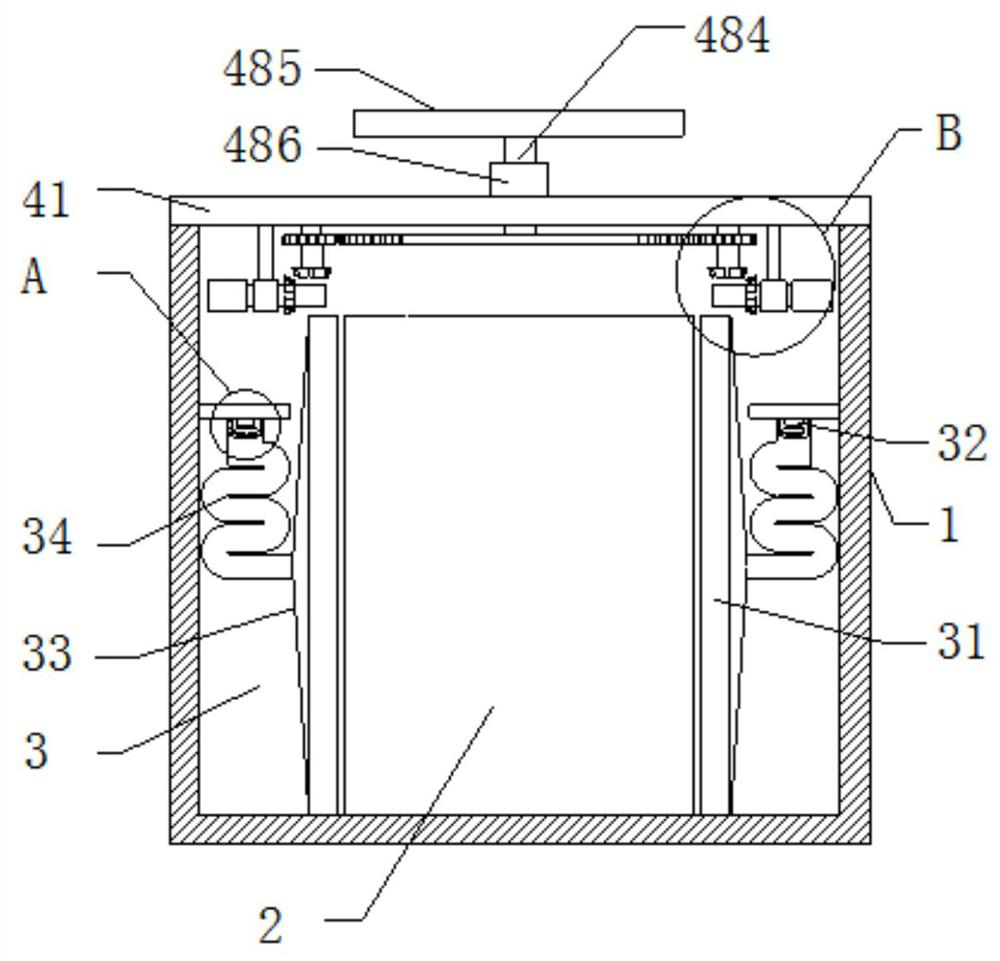
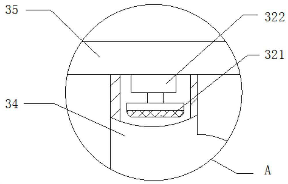
[0042] A key structure for a noise isolation device for power equipment, which is a noise isolation mechanism, including a honeycomb panel 31, the side of the honeycomb panel 31 away from the power equipment 2 is fixedly connected to a sound guide bucket 33, and the other end of the sound guide bucket 33 is fixedly connected There is a U-shaped tube 34, and the other end of the U-shaped tube 34 is fixedly connected with a noise reduction plate 35, and the side of the noise reduction plate 35 close to the U-shaped tube 34 is fixedly installed with a noise reduction module 32, and the noise reduction module 32 includes a noise reduction microphone 321 A calculation module 322 is fixedly connected to a side of the noise reduction microphone 321 close to the noise reduction board 35 , and the calculation module 322 is fixedly connected to the noise reduction board 35 .

[0043] The ...

Embodiment 3

[0045] This embodiment is an embodiment of the installation mechanism in the first embodiment.

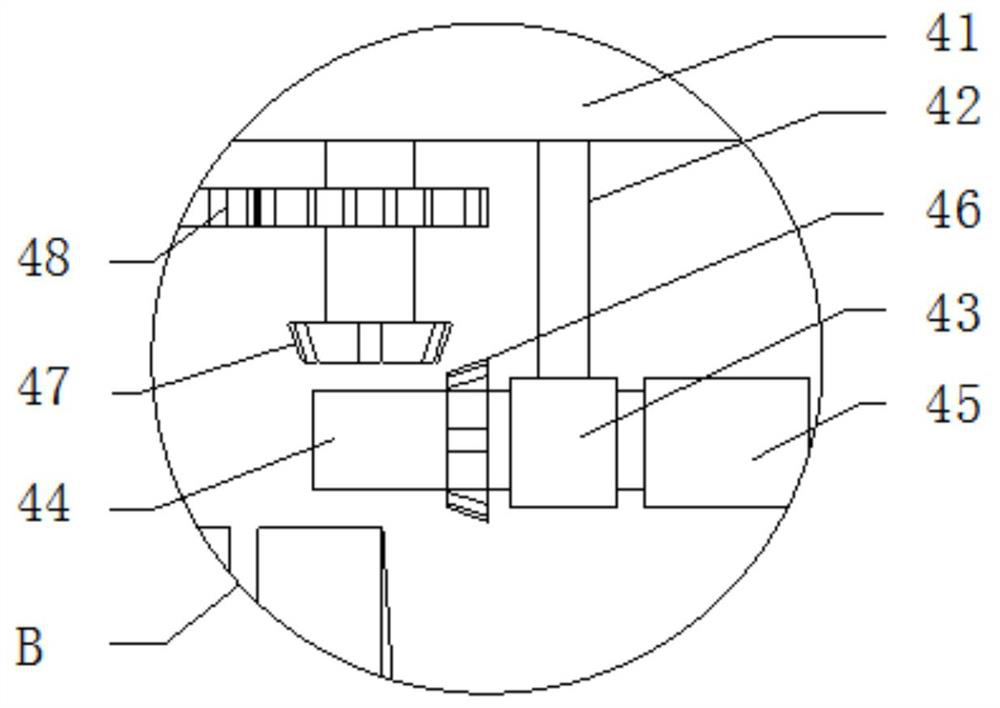
[0046] A key structure for a noise isolation device for power equipment, which is an installation mechanism, including an installation top plate 41, and both sides of the bottom end of the installation top plate 41 are fixedly installed with installation columns 42, and the other end of the installation column 42 is fixedly connected with an installation sleeve 43 , the middle part of the mounting sleeve 43 is clamped with a threaded column 44, and one end of the threaded column 44 is threadedly connected to the limit column 45, and the outer surface of the other end of the threaded column 44 is fixedly installed with a driven bevel gear 46, and the top of the driven bevel gear 46 is driven. Connected with driving bevel gear 47, the top of driving bevel gear 47 is fixedly connected with adjusting mechanism 48, and adjusting mechanism 48 comprises synchronous column 481, and the bott...


PUM


Abstract

The invention relates to the technical field of power equipment, and discloses a power equipment noise isolation device which comprises a device shell, power equipment is arranged in the device shell, a noise isolation device is arranged on the outer side of the power equipment, and a mounting device is arranged at the top end of the power equipment. The noise isolation device comprises a cellular board, the side, away from the power equipment, of the cellular board is fixedly connected with a sound guide hopper, the other end of the sound guide hopper fixedly communicates with a U-shaped pipe, the other end of the U-shaped pipe is fixedly connected with a noise reduction board, and a noise reduction module is fixedly installed on the side, close to the U-shaped pipe, of the noise reduction board. According to the noise isolation device for the power equipment, through the arrangement of the mounting device and the structure in the mounting device, the power equipment can be conveniently connected with the device shell, so that subsequent isolation, noise reduction and other treatment on noise are facilitated, the noise isolation device has the advantages of being convenient to mount and the like, and the problem that existing mounting is troublesome is solved.

Description

technical field [0001] The invention relates to the technical field of electric equipment, in particular to a noise isolation device for electric equipment. Background technique [0002] Power equipment mainly includes power generation equipment and power supply equipment. Power generation equipment is mainly power plant boilers, steam turbines, gas turbines, water turbines, generators, transformers, etc. Power supply equipment is mainly transmission lines of various voltage levels, transformers, contactors, etc. Switches, etc., because the power equipment will generate a lot of noise when it is working, it is necessary to use a noise isolation device to isolate the noise. [0003] However, most of the existing noise isolation devices for power equipment are cumbersome to install and have certain limitations. Therefore, we propose a noise isolation device for power equipment to solve the above technical problems. Contents of the invention [0004] (1) Solved technical pro...

Claims


Application Information

Patent Timeline
Patent Type & Authority Applications(China)
IPC IPC(8): G10K11/16G10K11/162G10K11/178
CPCG10K11/16G10K11/162G10K11/178G10K2210/121
Inventor 张立根
Owner 太湖县全的电器有限公司
Why Eureka
Try Eureka