High-safety barrier clearing equipment for power transmission line
What is Al technical title?
Al technical title is built by PatSnap Al team. It summarizes the technical point description of the patent document.
A technology for cleaning equipment and transmission lines, applied in the field of electric power, can solve the problems of poor safety, labor and time consumption, loss of life and production, and achieve the effect of high safety and easy tracking
Inactive Publication Date: 2021-04-13
史婧婧
View PDF0 Cites 1 Cited by
Summary
Abstract
Description
Claims
Application Information
AI Technical Summary
This helps you quickly interpret patents by identifying the three key elements:
Problems solved by technology
Method used
Benefits of technology
Problems solved by technology
Structural form, transmission lines are divided into overhead transmission lines and cable lines. Overhead transmission lines are composed of line towers, wires, insulators, line fittings, guy wires, tower foundations, grounding devices, etc., and are erected on the ground. According to the nature of the transmission current, Power transmission is divided into AC transmission and DC transmission. In daily work, there will inevitably be some obstacles around the transmission line, such as surface adhesions, hanging objects such as kite strings and plastic bags, and growing objects such as branches. , if these obstacles are not cleaned up in time, it is very easy to cause the danger of short circuit or even line breakage, causing unnecessary losses to people's life and production
[0003] At present, most of the obstacles on transmission lines are cleaned up by professional personnel through high-altitude operations. This cleaning method is not safe, and it consumes manpower and time, and it is difficult to meet people's needs.
Method used
Image
Click on the blue label to locate the original text in one second.
Reading with bidirectional positioning of images and text.
Examples
Embodiment Construction
[0021] The following will clearly and completely describe the technical solutions in the embodiments of the present invention with reference to the accompanying drawings in the embodiments of the present invention. Obviously, the described embodiments are only some, not all, embodiments of the present invention. Based on the embodiments of the present invention, all other embodiments obtained by persons of ordinary skill in the art without making creative efforts belong to the protection scope of the present invention.
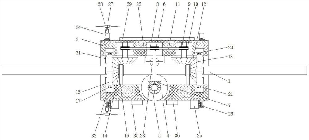
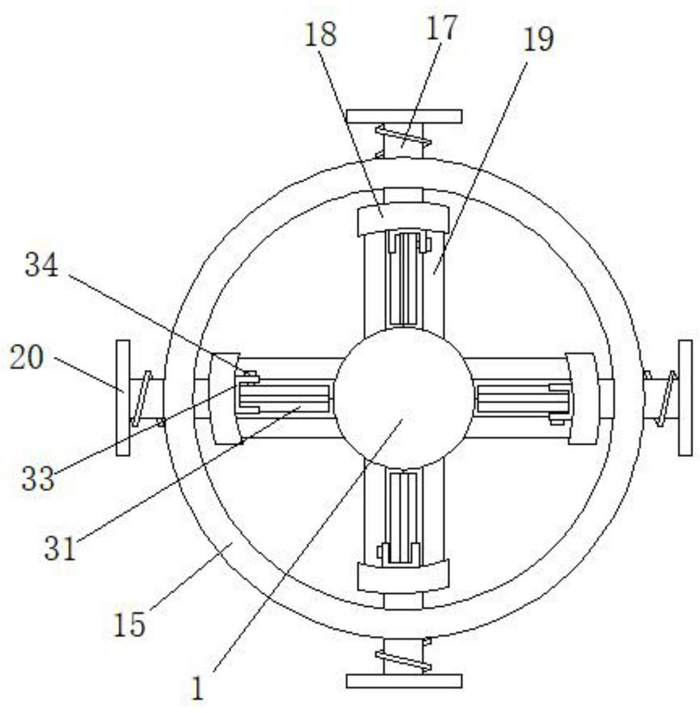
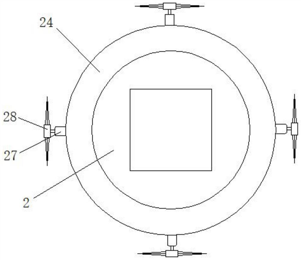
[0022] see Figure 1~4 , in an embodiment of the present invention, a high-safety obstacle cleaning device for power transmission lines includes a wire body 1, an organic body 2 is arranged on the surface of the wire body 1, and a first motor 3 is fixedly connected inside the body 2. The first The front end of the rotating shaft of the motor 3 is fixedly connected with the rotating wheel 4, the front of the rotating wheel 4 is fixedly connected with the first ...
PUM
Abstract
The invention discloses high-safety barrier cleaning equipment for a power transmission line in the field of power. The equipment comprises a wire body, the surface of the wire body is provided with a machine body, and the interior of the machine body is fixedly connected with a first motor. The machine body can move on the wire body through the first motor, the rotating wheel, the fixing frame and the pressing wheel, the fixing sleeve can be driven to rotate through the first gear, the second gear, the fixing rod, the first rotating cylinder, the connecting rod, the second rotating cylinder, the belt, the third gear and the fourth gear, through the connecting sleeve, the movable rod, the arc-shaped plate, bristles and a cutter, a kite line on the wire body can be cut off, the wire body is cleaned, plants can be cut through the gear ring, the second motor, the driving gear, the third motor and the cutting disc, time and labor are saved, safety is high, the requirements of people can be met, and use of people is facilitated.
Description
technical field [0001] The invention relates to the field of electric power, in particular to a high-safety obstacle cleaning device for power transmission lines. Background technique [0002] The transmission line is realized by using a transformer to boost the electric energy generated by the generator, and then connecting it to the transmission line through control equipment such as a circuit breaker. Structural form, transmission lines are divided into overhead transmission lines and cable lines. Overhead transmission lines are composed of line towers, wires, insulators, line fittings, guy wires, tower foundations, grounding devices, etc., and are erected on the ground. According to the nature of the transmission current, Power transmission is divided into AC transmission and DC transmission. In daily work, there will inevitably be some obstacles around the transmission line, such as surface adhesions, hanging objects such as kite strings and plastic bags, and growing ob...
Claims
Application Information
Patent Timeline
Application Date:The date an application was filed.
Publication Date:The date a patent or application was officially published.
First Publication Date:The earliest publication date of a patent with the same application number.
Issue Date:Publication date of the patent grant document.
PCT Entry Date:The Entry date of PCT National Phase.
Estimated Expiry Date:The statutory expiry date of a patent right according to the Patent Law, and it is the longest term of protection that the patent right can achieve without the termination of the patent right due to other reasons(Term extension factor has been taken into account ).
Invalid Date:Actual expiry date is based on effective date or publication date of legal transaction data of invalid patent.