Instrument for surgical assistance robot
A robot and surgery technology, which is applied in the field of surgical auxiliary robot equipment, can solve problems such as complex structures, and achieve the effects of simplifying structures, achieving stabilization, and constant movement
- Summary
- Abstract
- Description
- Claims
- Application Information
AI Technical Summary
Problems solved by technology
Method used
Image
Examples
reference example 1
[0041] [Structure of curved structure]
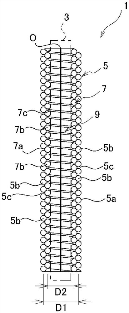
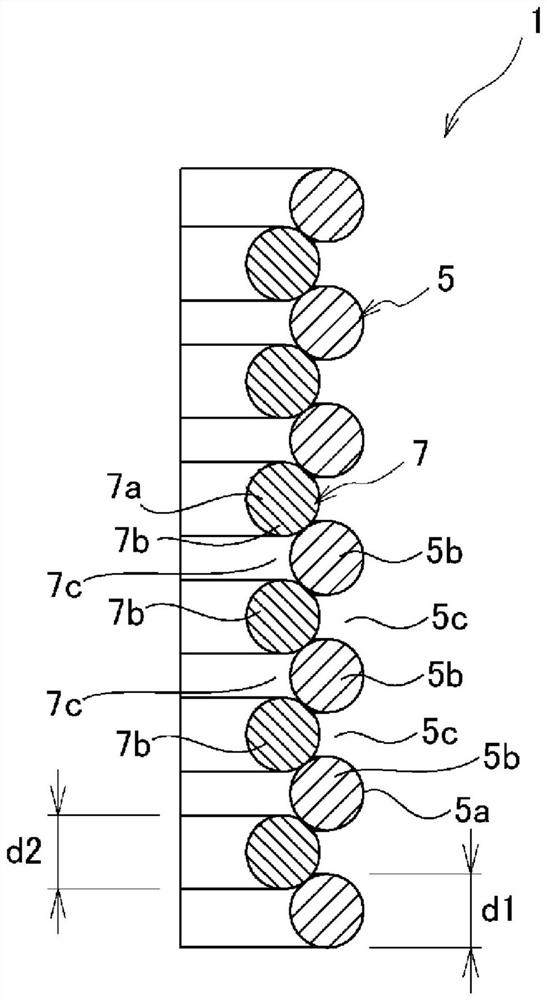
[0042] figure 1 It is a sectional view showing the bending structure of the flexible member of Reference Example 1 of the present invention, figure 2 is an enlarged view showing a part thereof.
[0043] The curved structure 1 is applied to, for example, joint functional parts of robots, manipulators, or actuators in various fields. The curved structure 1 is provided between the base of the joint function part and the movable part, and supports the movable part so as to be displaceable relative to the base by bending.
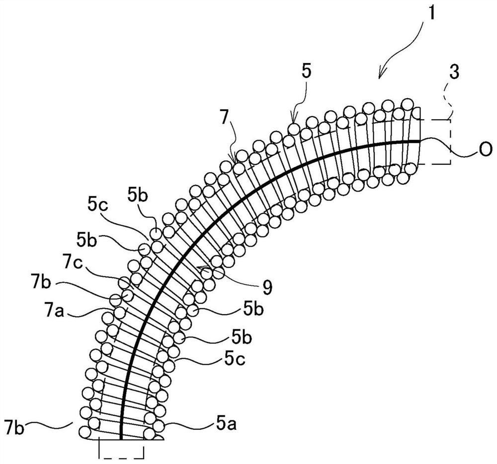
[0044] The curved structure 1 of this reference example has a double coil shape and includes an outer coil portion 5 and an inner coil portion 7 . With this double coil shape, the curved structure 1 of this reference example is configured to be able to bend relative to the axial direction, and when bent by an external force, the inner diameter side of the bend shrinks and the outer diameter side of the bend expands, s...
reference example 2
[0101] Figure 7 It is an enlarged cross-sectional view showing a part of the curved structure of Reference Example 2. FIG. In addition, in reference example 2, the same code|symbol is attached|subjected to the structure corresponding to reference example 1, and overlapping description is abbreviate|omitted.
[0102] In the curved structure 1 of Reference Example 2, the wire diameter d1 of the wire 5 a of the outer coil portion 5 and the wire diameter d2 of the wire 7 a of the inner coil portion 7 are different. In Reference Example 2, the wire diameter d1 of the outer coil portion 5 is made larger than the wire diameter d2 of the inner coil portion 7 . In addition, the wire diameter d1 of the outer coil portion 5 can also be made smaller than the wire diameter d2 of the inner coil portion 7 .
[0103] Even if the bent structure 1 is made to differ in the wire diameter d1 of the outer coil portion 5 and the wire diameter d2 of the inner coil portion 7 , the same effect as th...
reference example 3
[0105] Figure 8 It is an enlarged cross-sectional view showing a part of the curved structure of Reference Example 3. FIG. In addition, in reference example 3, the same code|symbol is attached|subjected to the structure corresponding to reference example 1, and redundant description is abbreviate|omitted.
[0106] In the curved structure 1 of Reference Example 3, in a part of the axial direction of the outer coil portion 5, the rolled portion 7b of the inner coil portion 7 is in contact with the adjacent rolled portion 5b of the outer coil portion 5, and is fitted into these. Between adjacent rolls 5b.
[0107] That is, the inner coil portion 7 is formed to have a center diameter D2 (refer to figure 1 ) gradually decreases in the axial direction. Accordingly, as described above, the inner coil portion 7 is fitted only partially in the axial direction between the adjacent coil portions 5 b of the outer coil portion 5 .
[0108] In addition, in this reference example, the i...
PUM
 Abstract
Description
Claims
Application Information
 - R&D
- Intellectual Property
- Life Sciences
- Materials
- Tech Scout
- Unparalleled Data Quality
- Higher Quality Content
- 60% Fewer Hallucinations
Browse by: Latest US Patents, China's latest patents, Technical Efficacy Thesaurus, Application Domain, Technology Topic, Popular Technical Reports.
© 2025 PatSnap. All rights reserved.Legal|Privacy policy|Modern Slavery Act Transparency Statement|Sitemap|About US| Contact US: help@patsnap.com


