
Pelvic surgery retractor

A technology of surgical retractor and pelvis, which is applied in the field of medical equipment, can solve problems such as easy slipping, achieve good vision, increase stability, and achieve the effect of light transmission

Pending Publication Date: 2021-04-16
THE THIRD HOSPITAL OF HEBEI MEDICAL UNIV +1
View PDF14 Cites 0 Cited by
  • Summary
  • Abstract
  • Description
  • Claims
  • Application Information

AI Technical Summary

Problems solved by technology

Due to the smooth surface of the traditional surgical retractor, it is easy to slip when in contact with bone tissue

Method used


Image

  • Pelvic surgery retractor
  • Pelvic surgery retractor
  • Pelvic surgery retractor

Examples


Embodiment 1

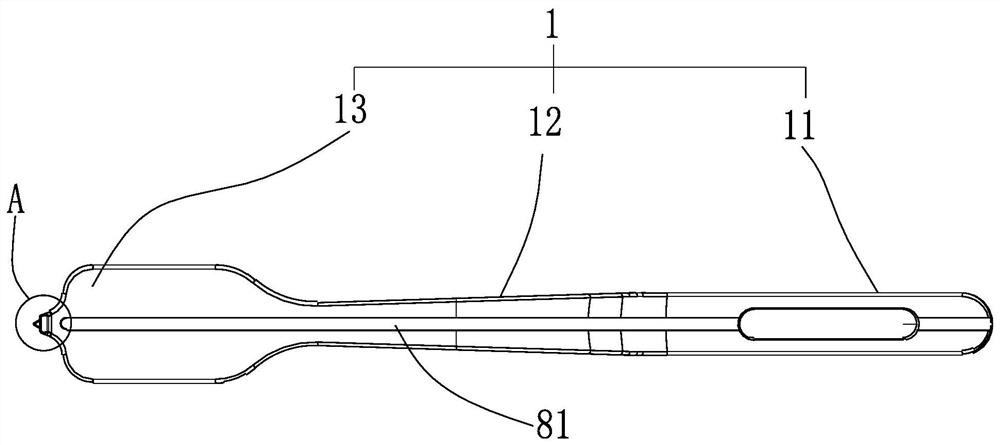
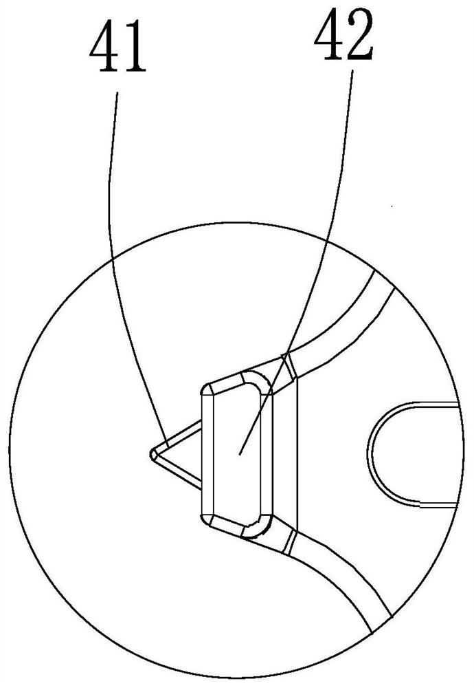
[0038] like Figure 1-8 As shown: the limiting structure is a blade 41 provided at the far end of the hook 13 and a convex edge 42 extending left and right, and the convex edge 42 is disposed below the hook 13 and near the blade 41 . Here, the extending direction of the blade in the blade portion is the up-down direction.

[0039] Described blade portion 41 is provided with one or two, when blade portion 41 is provided with one, blade portion 41 is arranged on the middle part of hook portion 13; arranged.

[0040] This structure can be applied to relatively flat areas in the pelvis, such as the pubic pectin, iliac fossa, etc.

[0041] Adjust the number of blades and the number of convex edges according to the size of the area. If it is used for the operation of the pubic comb, generally one blade 41 can be configured, and if it is used for the operation of the iliac fossa, generally two blades 41 can be configured.

[0042] When necessary, at least one needle guide hole 43 ...

Embodiment 2

[0044] like Figure 9-10 As shown: the limiting structure is a notch 51 provided at the distal end of the hook portion 13, and the contour of the notch 51 fits the anatomical structure of the arcuate wire.

[0045] This design is mainly aimed at the fixation of the arcuate wire. By fitting the arcuate wire, the friction force can be increased to reduce the occurrence of slipping.

Embodiment 3

[0047] like Figure 11-13 As shown: the position-limiting structure is a groove 61 extending left and right at the distal end, and the inner contour of the groove 61 fits the anatomical structure at the greater sciatic notch.

[0048] This design is mainly aimed at the fixation of the greater sciatic notch. By fitting it to the greater sciatic notch, the friction force can be increased to reduce the occurrence of slippage.

[0049] The contours of the upper groove wall 611 and the lower groove wall 612 of the groove 61 are M-shaped, so that the upper groove wall 611 and the lower groove wall 612 both form two sharp points 613 distributed left and right.

[0050] By adding the tip structure, it can ensure that the groove 61 and the greater sciatic notch are not fully anastomosed, and the tip can be used to assist grasping, improve the grasping ability of the retractor, and further reduce the possibility of slipping.

[0051] For the application of the above-mentioned limiting ...


PUM


Abstract

The invention provides a pelvic surgery retractor. A main body of the pelvis surgery retractor is a retractor, the retractor comprises a handheld part at the near end, a trunk part in the middle and a hook part at the far end, and the hook part is provided with a limiting structure which enables the hook part to be attached to the pelvis and prevents the hook part from slipping off. The pelvis retractor has the advantages that the retractor can be well grasped in the main area of the pelvis, such as the pubis comb, the arcuate line, the fossa iliaca and the large ischial incisura, and the retractor is prevented from slipping when bone tissue of the retractor makes contact with the pelvis; that is, the limiting structures of different shapes are designed according to the anatomical structures of different areas in the pelvis, so that the hook part of the drag hook can clamp or be attached to the special-shaped anatomical part of the pelvis, and the stability is improved. In addition, the handheld part is additionally provided with an anti-skid groove / hole design, so that the retractor is stable to hold without slipping off during an operation.

Description

technical field [0001] The invention relates to the field of medical instruments, in particular to a non-slip pelvic operation drag hook. Background technique [0002] Due to the continuous development of modern society and transportation, the incidence of pelvic and acetabular fractures caused by high-energy injury car accidents and falls from heights is on the rise. The anatomy of the human pelvic acetabulum is complex and can produce many different types of displacement depending on the mechanism of injury. Due to the large number of muscle attachments in different directions around the pelvis, surgical exposure and fracture reduction are quite difficult, especially for old displacement fractures. [0003] In recent years, minimally invasive surgery has developed rapidly. Minimally invasive surgery requires small surgical incisions, short operation time, and small soft tissue damage, so that patients can recover as soon as possible. The above requirements greatly increa...

Claims


Application Information

Patent Timeline
IPC IPC(8): A61B17/02A61B90/30
Inventor 侯志勇张英泽
Owner THE THIRD HOSPITAL OF HEBEI MEDICAL UNIV
Learn More