
Hip joint assisting walking mechanism

A walking mechanism, hip joint technology, used in appliances to help people move, physical therapy, etc., can solve problems such as inability to use for a long time, affecting exercise ability, and difficulty in climbing or stair climbing.

Inactive Publication Date: 2021-04-16
李红才
View PDF0 Cites 3 Cited by
  • Summary
  • Abstract
  • Description
  • Claims
  • Application Information

AI Technical Summary

Problems solved by technology

When most elderly people reach a certain age, their physical functions are greatly weakened, and they have difficulty walking, climbing slopes or stairs, unable to stand or walk for a long time, and even need to rely on wheelchairs and other equipment for daily living activities, which greatly affects their lives. Happiness
[0004] At present, the existing human lower limb assisting devices are mainly various exoskeleton robots. Most of the existing hip joint designs are based on series structures, which are directly driven by motors or hydraulic cylinders. Although this design method has a certain assisting effect , but for the whole system, the boosting effect is relatively small, and the use of active drive will increase the volume and weight of the exoskeleton robot, which will cause more unnecessary work and limit the range of motion; there are also some exoskeletons The hip joint of the robot is passively driven without any power source, and is completely driven by the wearer. This will undoubtedly increase the consumption of human body energy. Although the whole system has a certain boosting effect, the human body needs to overcome the gravity of the exoskeleton to do work. It will affect the ability to exercise, and it uses common bandages or Velcro to clamp the hip joints and legs, and the bandages or Velcro will be detached or loosened during exercise, so it is difficult to stick tightly to the human body fit, cannot be used for a long time

Method used


Image

  • Hip joint assisting walking mechanism
  • Hip joint assisting walking mechanism
  • Hip joint assisting walking mechanism

Examples


Embodiment Construction

[0030] The following will clearly and completely describe the technical solutions in the embodiments of the present invention with reference to the accompanying drawings in the embodiments of the present invention. Obviously, the described embodiments are only some, not all, embodiments of the present invention. All other embodiments obtained by persons of ordinary skill in the art based on the embodiments of the present invention belong to the protection scope of the present invention.

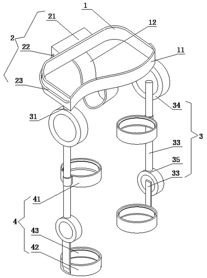
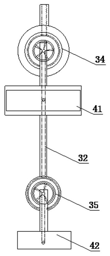
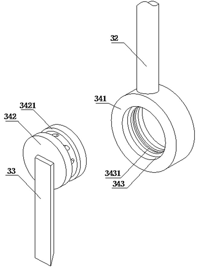
[0031] See attached Figure 1-6 A hip-assisted walking mechanism is shown, including a hip joint frame 1, an inflatable mechanism 2, an arm mechanism 3 and a lower limb limit mechanism 4, the outer wall of the hip joint frame 1 is connected with the inflatable mechanism 2, and the two parts of the hip joint frame 1 Each end is connected with the support arm mechanism 3, the lower limb limit mechanism 4 is fixed on two groups of opposite support arm mechanisms 3, and the inflatable mechanism 2...


PUM


Abstract

The invention discloses a hip joint assisting walking mechanism. The hip joint assisting walking mechanism comprises a hip joint frame, inflation mechanisms, supporting arm mechanisms and lower limb limiting mechanisms, wherein the outer wall of the hip joint frame is connected with the inflation mechanism; the two ends of the hip joint frame are connected with the supporting arm mechanisms respectively; the lower limb limiting mechanisms are fixed to the two opposite supporting arm mechanisms; and the inflation mechanisms penetrate through the supporting arm mechanisms to be connected with the lower limb limiting mechanisms. According to the hip joint assisting walking mechanism, airflow of an air pump flows into an annular groove position through an upper arm, a part of air is inflated into an air bag of a thigh ring, the airflow of the air pump flows into the annular groove position through the upper arm, the other part of the air is inflated into an air bag of a shank ring through an annular groove of a middle arm, and expansion or contraction of the air bags is controlled, so the air bags can clamp the leg during expansion; and pressure sensors are matched for use, so the problems of insufficient blood supply caused by long-time clamping of the leg due to excessive pressure of the air bags or easiness in falling off due to relatively slight clamping force between the air bags and the leg are solved.

Description

technical field [0001] The invention relates to the field of power-assisted walking mechanisms, in particular to a hip joint power-assisted walking mechanism. Background technique [0002] Worldwide, there are a large number of patients with lower limb movement disorders of varying degrees. Due to the impaired lower limb movement ability, their quality of life is affected to a large extent. According to clinical medical research, reasonable and effective rehabilitation training can make some patients recover to a certain extent. [0003] In addition, with the increasing population aging, countries around the world need to spend huge material and financial resources every year to solve many problems caused by population aging. When most elderly people reach a certain age, their physical functions are greatly weakened, and they have difficulty walking, climbing slopes or stairs, unable to stand or walk for a long time, and even need to rely on wheelchairs and other equipment ...

Claims


Application Information

Patent Timeline
IPC IPC(8): A61H3/00
Inventor 李红才
Owner 李红才
Learn More