Local reducing stirring head

A mixing head, local technology, applied in the field of local variable diameter mixing head, can solve the problems of affecting the quality of the weld, material overflowing the weld, intrusion of materials, etc.

Active Publication Date: 2021-04-16
安徽万宇机械设备科技有限公司
View PDF8 Cites 2 Cited by
  • Summary
  • Abstract
  • Description
  • Claims
  • Application Information

AI Technical Summary

Problems solved by technology

[0005] Therefore, the technical problem to be solved by the present invention is to overcome the defects in the prior art that the front shoulder of the stirring head will intrude into the material during friction stir welding of curved surfaces and affect the quality of the weld seam, and the single small shoulder stirring head will easily cause the material to overflow the weld seam , so as to provide a partially variable-diameter stirring head and welding equipment having the same

Method used


Image

  • Local reducing stirring head
  • Local reducing stirring head
  • Local reducing stirring head

Examples


Embodiment 1

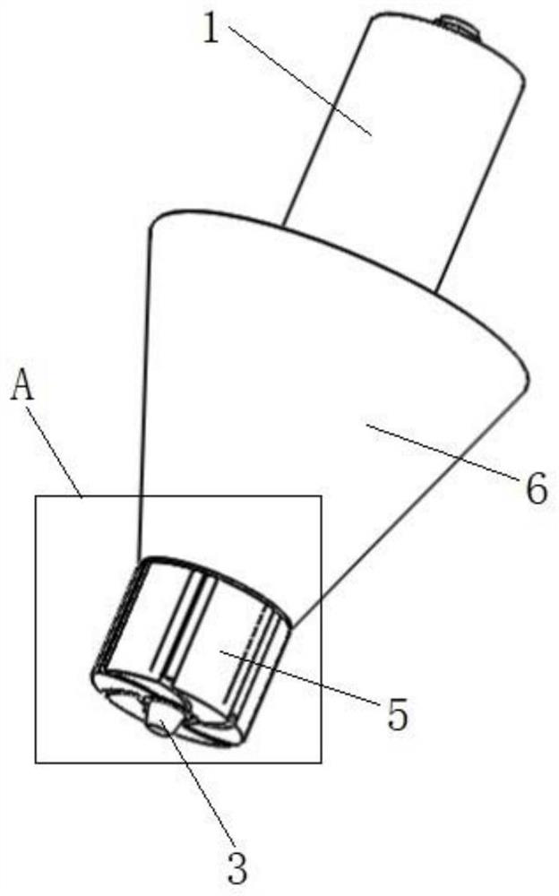
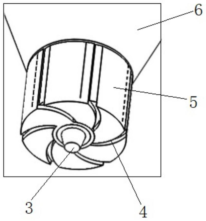
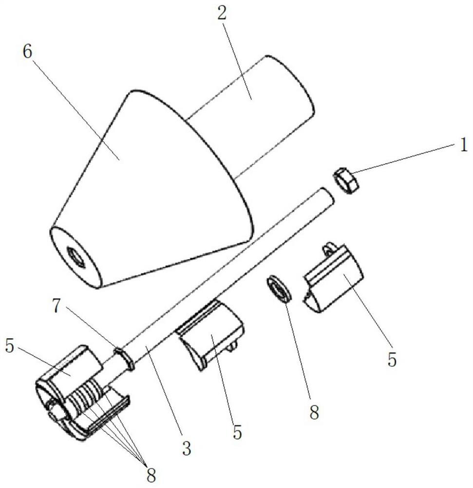
[0031] Such as Figure 1-6 As shown, this embodiment provides a partially variable-diameter stirring head, which includes a stirring needle 3, a shaft shoulder, a stirring head transition end 6 and a clamping end 2, and the shaft shoulder, the stirring head transition end 6 and the clamping end 2 Pass through the stirring pin 3 sequentially from bottom to top, and be locked and fixed by the fastening nut 1 of the stirring head as the second fastener; wherein, the shoulder includes several moving shoulder blocks 5; The moving shoulder block 5 is pivotally connected to the stirring needle with the stirring needle as a pivot, and the stirring needle plays the role of installation and positioning; the inner side of each moving shoulder block 5 has an arc-shaped surface 15, The arc-shaped surface 15 is used as a cladding surface, and it overlaps the outer side of the adjacent moving shoulder block 5. Preferably, the adjacent moving shoulder block 5 has an arc-shaped surface 15 on t...

Embodiment 2

[0039] This embodiment provides a friction stir welding equipment, including a driving motor, a main shaft and a stirring head, wherein the stirring head is the locally variable-diameter stirring head described in Embodiment 1. The friction stir welding equipment provided in this embodiment is suitable for reducing the shoulder intrusion during friction stir welding of curved surfaces, and effectively improving welding quality. When welding materials, under the action of the main shaft rotation, the stirring head rotates to generate centrifugal force, and the moving shoulder block is thrown out to reach the maximum diameter state. When the end point of the convex surface or the lowest point of the concave surface of the stirring needle as the base point, the front end of the shoulder of the stirring head touches the welding material, and the moving shoulder block is subjected to the resistance of the material to it, and the resistance counteracts the centrifugal force and shrin...


PUM


Abstract

The invention relates to the technical field of friction stir welding, in particular to a local reducing stirring head. The local reducing stirring head is provided with a stirring needle and a shaft shoulder. The shaft shoulder comprises a plurality of movable shaft shoulder blocks which are connected to the stirring needle in a pivoted mode. The inner side of each movable shaft shoulder block is provided with an arc-shaped face which is connected to the outer side of an adjacent movable shaft shoulder block in a lap joint mode. An arc-shaped gap is formed between the bottom edges of every two adjacent movable shaft shoulder blocks, and the width of each arc-shaped gap can be changed along with different pivoting motion of the movable shaft shoulder blocks on the two sides, so that the multiple arc-shaped gaps with the variable widths are formed in the working end face of the shaft shoulder and can reduce the shaft shoulder invasion amount during curved surface friction stir welding, the shaft shoulder diameter can be partially changed without the need of shaft shoulders of multiple sizes to be installed, and the welding efficiency can be effectively improved.

Description

technical field [0001] The invention relates to the technical field of friction stir welding, in particular to a locally variable-diameter stirring head. Background technique [0002] Friction stir welding (FSW) is an advanced welding technology, which has the advantages of low welding stress, green and pollution-free, and is widely used in aerospace, automobile and ship fields. Traditional FSW welding is carried out on the gantry type FSW welding machine, but the gantry type FSW welding machine only has three moving directions of XYZ, and can only perform conventional two-dimensional welding. In the actual production process, various complex three-dimensional curved surface workpieces are used. In order to realize the welding of these three-dimensional curved surface workpieces, scholars have proposed a FSW robot welding machine technology. The FSW robot has multiple degrees of freedom and can realize various complex surface welding. [0003] When FSW robot is welding, in...

Claims


Application Information

Patent Timeline
Patent Type & Authority Applications(China)
IPC IPC(8): B23K20/12B23K20/26
Inventor 万龙温琦黄体方黄永宪
Owner 安徽万宇机械设备科技有限公司
Why Eureka
Try Eureka