Push rod structure of upper thread clamping device and upper thread clamping device of embroidery machine

A clamping device and clamping structure technology, applied in the field of embroidery machines, can solve the problems of limited side space, the inability of the electromagnet to drive the ejector rod, affecting the normal installation of the upper thread clamping device, etc., so as to avoid interference and avoid the influence of installation. Effect

Pending Publication Date: 2021-04-16
ZHEJIANG XINSHENG SEWING EQUIP
View PDF0 Cites 2 Cited by
  • Summary
  • Abstract
  • Description
  • Claims
  • Application Information

AI Technical Summary

Problems solved by technology

[0004] However, when the electromagnet is used to drive the ejector pin, due to the limited space on the side of the machine head, the normal installation of the upper thread clamping device will be affected.
In addition, when the embroidery machine uses partition embroidery, the electromagnet cannot drive the ejector rod corresponding to the partition embroidery needle rod, which cannot meet the working requirements of the embroidery machine well.

Method used


Image

  • Push rod structure of upper thread clamping device and upper thread clamping device of embroidery machine
  • Push rod structure of upper thread clamping device and upper thread clamping device of embroidery machine
  • Push rod structure of upper thread clamping device and upper thread clamping device of embroidery machine

Examples


Embodiment 1

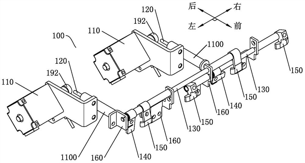
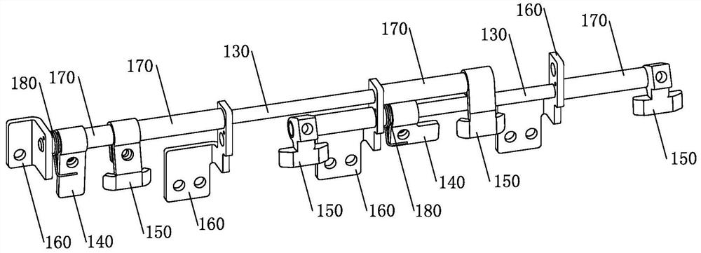
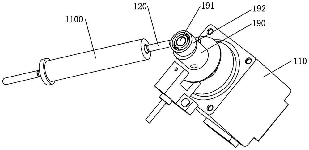
[0035] Such as Figure 1 to Figure 4 As shown, Embodiment 1 of the present invention provides a push rod structure of a needle thread clamping device. The push rod structure 100 comprises a motor 110, a push rod 120, a rotating shaft 130, a push piece 140 and a blocking piece 150. The front end of rod 120 conflicts with push piece 140, and motor 110 can drive push rod 120 to move forward.

[0036] The left-right direction shown in the figure is the horizontal direction, and the front-rear direction and the left-right direction are set vertically on the horizontal plane. The axial direction of the rotating shaft 130 is arranged along the left-right direction, and the axial direction of the push rod 120 is arranged along the front-rear direction, that is, the push rod 120 is arranged vertically to the rotating shaft 130 .

[0037] In order to install the rotating shaft 130, the push rod structure also includes a fixed seat 160, the fixed seat 160 is provided with a through hol...


PUM


Abstract

The invention discloses a push rod structure of an upper thread clamping device and the upper thread clamping device of an embroidery machine, and belongs to the technical field of embroidery machines. The push rod structure comprises a motor, a push rod, a rotating shaft, a push piece and a baffle piece, wherein the push rod can move back and forth; the rotating shaft is transversely arranged; the push piece and the baffle piece are arranged on the rotating shaft; the front end of the push rod abuts against the push piece; the motor can push the push rod to move forwards; and when the push rod moves forwards, the push rod abuts against the push piece to drive the rotating shaft to rotate, so that the baffle piece is warped and rotated forwards. The motor of the push rod structure can be installed behind a machine head, the rotating shaft can be rotatably arranged on the machine head, and the installation positions of all the components of the push rod structure are reasonably arranged, so that the interference caused by the push rod structure to an upper thread clamping structure and a needle bar frame can be effectively avoided, and the installation influence caused by the push rod structure to the upper thread clamping structure is avoided.

Description

technical field [0001] The invention relates to the technical field of embroidery machines, in particular to a push rod structure of an upper thread clamping device. In addition, the invention also relates to an upper thread clamping device adopting the push rod structure. Background technique [0002] In the embroidery machine industry, with the improvement of product performance and fabric aesthetics requirements, the requirements for product quality and efficiency have doubled, so it is necessary to ensure the stability of embroidery machine upper thread clamping. The upper thread clamping device is the main part of the embroidery machine. Its function is to cooperate with the embroidery machine to realize the operation of clamping or loosening the upper thread, and effectively solve the problem that the upper thread is easy to fall out of the pinhole during thread trimming, color changing, and mending embroidery. problems, to help embroidery machines improve embroidery e...

Claims


Application Information

Patent Timeline
Patent Type & Authority Applications(China)
IPC IPC(8): D05C11/08
Inventor 王海江田桂郁
Owner ZHEJIANG XINSHENG SEWING EQUIP
Why Eureka
Try Eureka